
Why MIM Is Ideal for Small, Complex, High-Volume Metal Parts
Published:
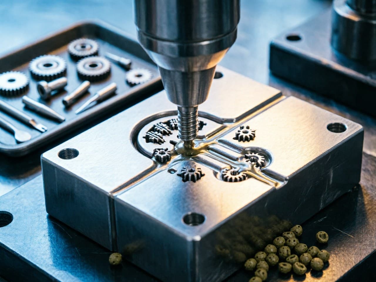
Why MIM Is Ideal for Small, Complex, High-Volume Metal Parts
The Manufacturing Dilemma: When Conventional Processes Hit Their Limits
Design engineers working on miniature metal components — from surgical instrument jaws to micro-gear trains in smartwatch movements — face a recurring frustration. The part is too geometrically complex for stamping, too small for efficient CNC machining, and demands material properties that zinc or aluminum die casting simply cannot deliver. As annual volumes climb into the hundreds of thousands or millions, the cost-per-part of subtractive methods becomes untenable, while tooling-based processes like investment casting struggle with the fine features and tight tolerances these applications require.
This is the exact design-manufacturing gap that Metal Injection Molding (MIM) was engineered to fill. But understanding why MIM excels in this niche — and more importantly, how to optimize your strategy around it — requires a closer look at the process economics, geometric capabilities, and material performance that set MIM apart.
Selection Comparison:
MIM vs. Alternative Processes for Small, Complex Parts
The table below compares MIM against the most common competing processes across the parameters that matter most when parts are small (typically < 50 g), geometrically complex, and needed at scale.
| Parameter | MIM | CNC Machining | Investment Casting | Stamping / Fine Blanking | PM (Press & Sinter) |
|---|---|---|---|---|---|
| Part weight sweet spot | 0.1 – 50 g | 1 g – no limit | 10 g – several kg | Flat/2.5D profiles | 5 – 200 g |
| Geometric complexity | Very high (undercuts, internal channels, thin walls) | High (but cost-driven) | Moderate–High | Low (2D/2.5D) | Low–Moderate |
| Typical tolerance | ±0.3 %–0.5 % of dimension | ±0.01 mm achievable | ±0.5 %–1.0 % | ±0.05 mm (in-plane) | ±0.1–0.3 mm |
| Relative density | ≥ 96 %–99 % | 100 % (wrought) | ~100 % | 100 % (wrought) | 85 %–92 % |
| Material breadth | Wide (stainless, low-alloy, tungsten alloys, soft magnetic, Ti) | Very wide | Wide (mostly ferrous & Ni-based) | Limited by formability | Iron-based, some Cu |
| Economical annual volume | > 5,000–10,000 pcs | 1–5,000 pcs | 500–50,000 pcs | > 100,000 pcs (simple shapes) | > 10,000 pcs |
| Unit cost trend at 500 k/yr | Very low | Very high | Moderate | Low (if geometry fits) | Low (if geometry fits) |
| Surface finish (as-produced) | Ra 0.8–1.6 µm | Ra 0.4–1.6 µm | Ra 3.2–6.3 µm | Ra 0.4–1.0 µm | Ra 1.6–3.2 µm |
Key takeaway: MIM dominates when three conditions converge — small size, three-dimensional complexity, and volume. Remove any one of these, and another process may compete. When all three are present, MIM typically delivers 30 %–60 % lower per-part cost than CNC machining while achieving near-wrought mechanical properties.
Quantitative Model: MIM vs. CNC Cost Crossover
The cost advantage of MIM over machining is not automatic — it depends on volume, part complexity, and tooling amortization. A simplified cost model illustrates the crossover:
Total unit cost (CNC):
where t_cycle is cycle time per part (minutes), R_machine is the fully loaded machine-hour rate (USD/min), and C_material,bar is bar-stock material cost per part.
Total unit cost (MIM):
where C_tool is the one-time mold/tooling investment, N is total production quantity, C_feedstock is feedstock cost per part, and C_process covers injection, debinding, sintering, and QC on a per-part basis.
What this means for your decision:
- At low volumes (< 3,000–5,000 parts), the tooling denominator N keeps MIM unit cost high, and CNC wins. - As N grows, the tooling amortization drops rapidly, while CNC's t_cycle × R_machine remains essentially fixed per part. - For representative small stainless-steel components with moderate complexity, the crossover typically occurs between 5,000 and 20,000 annual units, after which MIM cost falls steeply relative to CNC. For highly complex parts requiring multi-axis machining, the crossover can shift to lower volumes.
This is why volume forecasting and design-for-MIM optimization at the concept stage are critical: they determine whether MIM's economics unlock or remain marginal.
Design Parameter Recommendations for MIM Optimization
Maximizing MIM's advantages requires designing with the process, not merely substituting an existing machined design. The following guidelines help engineers optimize parts for MIM producibility and cost:
Wall thickness: Target 0.3–3.0 mm for most alloys. Walls below 0.3 mm increase sintering distortion risk. Walls above 6 mm cause debinding challenges and extend cycle times.
Uniform cross-sections: Gradual transitions between thick and thin sections reduce differential shrinkage. Sintering shrinkage in MIM is typically 15 %–22 % linearly; non-uniform walls amplify dimensional scatter.
Draft angles: 0.5°–1° is generally sufficient (less than plastic injection molding) because the green part is ejected before significant shrinkage occurs in the mold.
Tolerances: Design to ±0.3 %–0.5 % of nominal. Where tighter tolerances are needed on specific features (e.g., bearing bores), plan for a secondary coining or machining operation on those features only — this is still far more economical than machining the entire part.
Feature integration: MIM's greatest cost lever is consolidation. A bracket that was previously an assembly of three stamped and welded pieces can often become a single MIM part, eliminating fasteners, fixtures, and assembly labor.
Material selection: MIM supports a wide material palette — 316L and 17-4PH stainless steels, Fe–Ni soft magnetic alloys, tungsten heavy alloys, and tungsten-copper composites. Choosing the right alloy system early avoids costly redesigns after prototyping.
The Newlife - MIM Optimization Advantage
Translating these design principles into production-ready parts requires a manufacturing partner with depth across the entire MIM value chain. Newlife - MIM offers capabilities directly relevant to the small-complex-high-volume challenge, including fine-powder feedstocks that support thinner walls and higher feature resolution in micro-components, production experience across stainless steel, iron-based, soft magnetic, and tungsten alloy systems, consistent near-net-shape sintering control for dimensional repeatability at scale, and capacity suited to high-volume programs.
Action Checklist: Optimizing Your Next Small, Complex Metal Part
1. Audit your current BOM — identify machined or assembled parts under 50 g with annual volumes above 5,000 units. These are prime MIM conversion candidates. 2. Apply the wall-thickness and uniformity guidelines above during concept design; avoid retrofitting MIM rules onto a machined geometry. 3. Run a rough cost-crossover estimate using the model in this guide to confirm MIM economics for your projected volumes. 4. Consolidate multi-piece assemblies into single MIM components wherever functional requirements allow — this is where the largest cost and reliability gains hide. 5. Specify material requirements by function, not by legacy habit — MIM's alloy breadth often opens options (e.g., switching from a brass machined part to a 316L MIM part for superior corrosion resistance at lower cost). 6. Engage Newlife - MIM early for joint DFM review and rapid prototyping. Visit https://www.kingmimpm.com to request a free engineering consultation and explore customized MIM solutions tailored to your application. The earlier MIM-specific design input enters your development cycle, the greater the cost, performance, and time-to-market advantage you will capture.
References
1. German, R. M. Metal Injection Molding: A Comprehensive MIM Design Guide. Metal Powder Industries Federation (MPIF), 2011. 2. MPIF Standard 35, Materials Standards for Metal Injection Molded Parts, 2018 edition. 3. Heaney, D. F. (ed.). Handbook of Metal Injection Molding, 2nd edition. Woodhead Publishing, 2019. 4. ASTM B883 – Standard Specification for Metal Injection Molded (MIM) Ferrous Materials. 5. Johnson, J. L. & German, R. M. "Powder Metallurgy Processing of Mo–Cu for Thermal Management Applications," International Journal of Powder Metallurgy, vol. 35, no. 3, 1999, pp. 39–48.
<!-- JSON-LD: {"@context": "https://schema.org", "@type": "TechArticle", "headline": "Why MIM Is Ideal for Small, Complex, High-Volume Metal Parts", "inLanguage": ["en", "zh"], "keywords": "why MIM is ideal for small complex metal parts, metal injection molding high volume production optimization, MIM vs CNC machining cost comparison small parts, complex geometry metal parts manufacturing strategy, MIM design optimization for miniature components", "about": [{"@type": "Thing", "name": ""}, {"@type": "Thing", "name": ""}], "author": {"@type": "Organization", "name": "Newlife - MIM", "alternateName": "新莱福MIM应用工程团队"}, "publisher": {"@type": "Organization", "name": "Newlife - MIM", "url": "https://www.kingmimpm.com"}} -->