
What Is MIM Feedstock? How to Match Binder Systems, Powder Loading, and Injection Molding Process
Published:
What Is MIM Feedstock? How to Match Binder Systems, Powder Loading, and Injection Molding Process
Application Pain Points:
Why Feedstock Formulation Determines MIM Part Quality
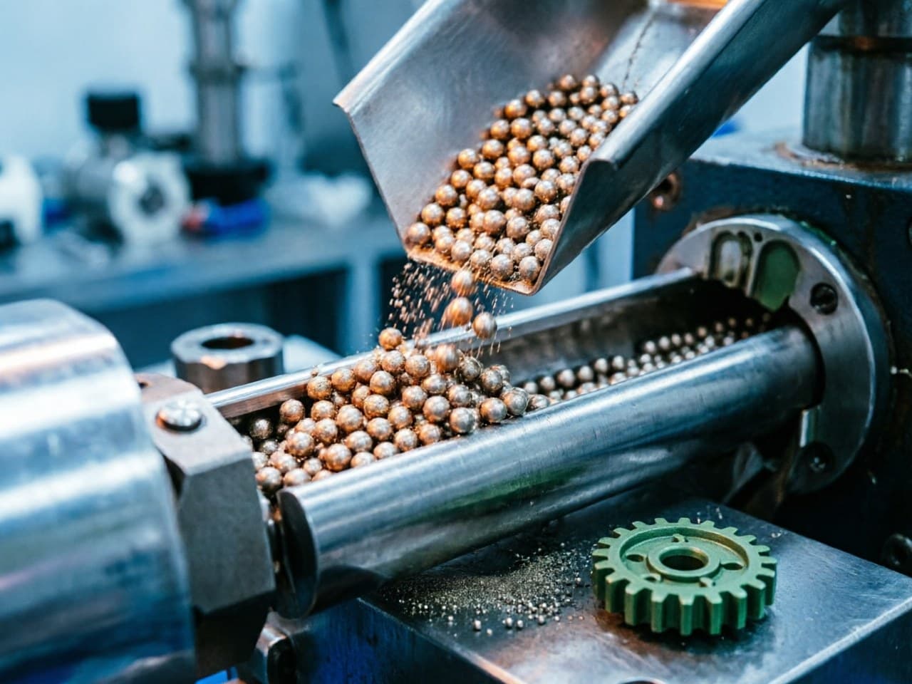
Metal Injection Molding (MIM) feedstock is the ready-to-inject mixture of fine metal powder and a multi-component binder system. It is the single most influential variable in the entire MIM process chain—determining whether a part can be molded without defects, whether it survives debinding without cracking, and whether it achieves target density after sintering.
Design engineers and procurement decision-makers frequently encounter these pain points when specifying or qualifying MIM feedstock:
- Injection defects (short shots, jetting, weld-line weakness) traced back to mismatched viscosity between binder rheology and powder loading. - Debinding failures (blistering, slumping, carbon residue) caused by incompatible binder decomposition sequences. - Dimensional scatter exceeding ±0.5% tolerance because powder loading was not optimized for the specific powder morphology and particle size distribution. - Supplier lock-in when proprietary feedstock systems prevent second-sourcing or material substitution.
Understanding the interplay among binder chemistry, powder volume fraction, and injection parameters is essential for making informed sourcing decisions and for collaborating effectively with MIM manufacturers during co-development.
Comparative Selection Table: Binder Systems for MIM Feedstock
| Criterion | Wax–Polyolefin (Wax-PO) | Polyacetal / POM-Based (Catalytic) | Water-Soluble (PEG-Based) | Gel-Based / Agar |
|---|---|---|---|---|
| Primary debinding method | Solvent (heptane/hexane) + thermal | Catalytic (HNO₃ or oxalic acid vapor) | Water leaching + thermal | Thermal only |
| Typical powder loading (vol%) | 55–65% | 60–66% | 55–63% | 50–60% |
| Green strength | Moderate | High | Low–Moderate | Low |
| Debinding speed (relative) | Medium | Fast | Medium–Fast | Slow |
| Shape retention during debinding | Good | Excellent | Moderate | Fair |
| Environmental / safety concern | Solvent VOC | Acid fume handling | Wastewater treatment | Minimal |
| Suitability for micro/thin-wall parts | Good | Excellent | Moderate | Limited |
| Common metal systems | Stainless steel, Fe–Ni, Ti | Stainless steel, tungsten alloys, soft magnetic | Stainless steel, Fe-based | Specialty ceramics, some metals |
| Feedstock shelf life | Long | Long | Moderate (moisture-sensitive) | Short |
Key Takeaway for Procurement: Catalytic (POM-based) systems dominate high-volume automotive and electronics production due to fast debinding and excellent dimensional control, but they require capital investment in acid-vapor furnaces. Wax-polyolefin systems offer broader material flexibility and lower entry cost. Water-soluble binders appeal to environmentally regulated facilities but demand tighter humidity control in storage and molding.
Quantitative Model:
Powder Loading, Viscosity, and the Critical Volume Fraction
Core Relationship — Feedstock Viscosity vs. Powder Loading
The effective viscosity of a MIM feedstock suspension follows a modified Krieger–Dougherty relationship:
Where:
- = feedstock viscosity (Pa·s) - = binder viscosity at processing temperature (Pa·s) - = actual powder volume fraction (powder loading) - = critical powder volume concentration (CPVC), the maximum packing fraction for the given powder (typically 0.62–0.68 for mono-modal spherical powders; up to 0.72–0.74 for bimodal distributions) - = intrinsic viscosity (≈2.5 for spheres)
What this means for the designer and buyer:
1. As approaches , viscosity rises sharply—injection pressure requirements increase non-linearly, risking incomplete fill in thin-wall geometries (< 0.3 mm). 2. Operating at ≈ 0.90–0.94 is the practical sweet spot: high enough to minimize sintering shrinkage and distortion, low enough to maintain moldability. 3. Selecting a powder with broader or bimodal particle size distribution (e.g., mixing D50 ≈ 8 µm with D50 ≈ 2 µm) raises , allowing higher loading at manageable viscosity—directly reducing sintering shrinkage from ~16–18% linear down to ~13–15%.
Shrinkage Estimation
Linear sintering shrinkage is approximated by:
Where is the target relative sintered density (e.g., 0.98 for ≥98% theoretical density).
Practical implication: Every 2 vol% increase in powder loading reduces linear shrinkage by roughly 0.8–1.0%, tightening as-sintered tolerances and reducing post-machining requirements. For a part with 20 mm nominal dimension, going from 60 vol% to 64 vol% loading reduces the shrinkage allowance from ~3.2 mm to ~2.6 mm—a meaningful gain for tight-tolerance assemblies.
Design Parameter Recommendations
| Parameter | Recommended Range | Notes |
|---|---|---|
| Powder loading (volume %) | 60–66% for POM-based; 55–63% for wax-PO | Higher loading = less shrinkage, but higher injection pressure |
| Powder D50 | 2–10 µm (fine powders preferred for micro-features) | Finer powder → better surface finish, higher sintered density |
| Melt temperature (injection) | 150–190 °C (varies by binder) | Must stay below binder decomposition onset |
| Mold temperature | 30–60 °C (wax-PO); 100–140 °C (POM) | Affects skin formation and weld-line strength |
| Injection pressure | 60–150 MPa | Driven by feedstock viscosity and part geometry |
| Gate velocity | 1–5 m/s | Avoid jetting; balance fill time vs. powder-binder separation |
| Wall thickness uniformity | Variation < 2:1 ratio | Minimizes differential shrinkage and distortion |
| Debinding rate ramp | ≤2 °C/min through binder burnout window | Prevents internal vapor pressure buildup → blistering |
Design Rule of Thumb: If your part has wall sections below 0.5 mm, specify a feedstock with D50 ≤ 5 µm and powder loading ≥ 62 vol% to ensure both moldability and post-sinter integrity. Discuss with your MIM supplier whether a bimodal powder blend can push loading higher without exceeding press tonnage limits.
Newlife - MIM Capabilities in Feedstock Development
Newlife - MIM supports feedstock optimization through integrated powder production and compounding. This enables tailored particle size distributions that improve packing density across stainless steels, iron-based alloys, soft magnetic materials, and tungsten alloys. Consistent control of powder loading and sintering profiles contributes to relative densities ≥ 98% and dimensional repeatability in the ±0.3%–0.5% range for suitable geometries. Full process ownership from compounding through sintering reduces interface risks between powder, binder, and molding stages.
Action Checklist for Engineers and Procurement Teams
1. Define your critical-to-quality dimensions — identify which tolerances truly require ±0.3% vs. where ±0.5% suffices; this drives powder loading and feedstock cost decisions.
2. Request feedstock data sheets — ask suppliers for viscosity-vs-shear-rate curves at processing temperature, powder loading certification, and TGA/DSC binder decomposition profiles.
3. Evaluate binder-debinding compatibility — match binder chemistry to your available debinding infrastructure (solvent, catalytic, or thermal-only) and throughput requirements.
4. Assess powder particle size distribution — confirm D50, D10/D90 span, and whether a bimodal blend is used; these directly affect surface finish and sintered density.
5. Run a pilot shrinkage study — before committing to production tooling, validate actual linear shrinkage against the predicted value from the loading/density formula above.
6. Contact Newlife - MIM for customized feedstock and engineering support — visit https://www.newlifematerial.com to request a free consultation. The Newlife - MIM application engineering team can provide tailored feedstock recommendations, DFM feedback on your part geometry, and rapid prototyping to validate your design before full-scale production.
References
1. German, R. M. Metal Injection Molding: A Comprehensive MIM Design Guide. Metal Powder Industries Federation (MPIF), 2011. 2. German, R. M. & Bose, A. Injection Molding of Metals and Ceramics. Metal Powder Industries Federation, 1997. 3. Krieger, I. M. & Dougherty, T. J. "A Mechanism for Non-Newtonian Flow in Suspensions of Rigid Spheres." Transactions of the Society of Rheology, 3(1), 137–152, 1959. 4. Heaney, D. F. (Ed.). Handbook of Metal Injection Molding, 2nd Edition. Woodhead Publishing, 2019. 5. ASTM B883-19. Standard Specification for Metal Injection Molded (MIM) Materials. ASTM International, 2019.
<!-- JSON-LD: {"@context": "https://schema.org", "@type": "TechArticle", "headline": "What Is MIM Feedstock? How to Match Binder Systems, Powder Loading, and Injection Molding Process", "inLanguage": ["en", "zh"], "keywords": "MIM feedstock binder system comparison, powder loading volume ratio MIM injection molding, MIM feedstock formulation design guide, binder debinding compatibility MIM process, metal injection molding feedstock powder loading optimization", "about": [{"@type": "Thing", "name": ""}, {"@type": "Thing", "name": ""}], "author": {"@type": "Organization", "name": "Newlife - MIM", "alternateName": "新莱福MIM应用工程团队"}, "publisher": {"@type": "Organization", "name": "Newlife - MIM", "url": "https://www.newlifematerial.com"}} -->