
What Is Metal Injection Molding (MIM)? Process Workflow, Suitable Parts, and Key Capability Indicators
Published:
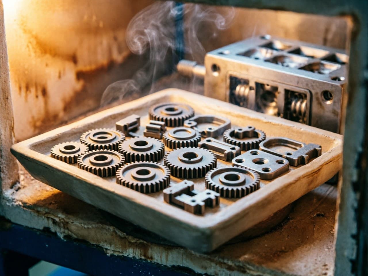
What Is Metal Injection Molding (MIM)? Process Workflow, Suitable Parts, and Key Capability Indicators
Application Pain Points:
Why Traditional Metalworking Falls Short for Complex Small Parts
Design engineers and procurement teams face a recurring challenge: producing small, geometrically complex metal parts at scale with consistent quality and controlled cost. Traditional manufacturing routes each carry inherent limitations:
- CNC machining delivers excellent precision but generates significant material waste (buy-to-fly ratios often exceed 5:1) and per-part cost escalates sharply with geometric complexity—internal channels, undercuts, and thin walls multiply setup and cycle time. - Investment casting handles complexity reasonably well but struggles to hold tight tolerances below ±0.1 mm on features under 5 mm, and surface finish often requires secondary operations. - Conventional powder metallurgy (PM) is cost-effective for simple shapes but is limited to 2.5D geometries and typically achieves only 85–92 % relative density, constraining mechanical performance. - Stamping and forming excel at high-volume sheet-metal parts but cannot produce three-dimensional solid geometries with variable cross-sections.
Metal Injection Molding (MIM) was developed precisely to bridge this gap—combining the geometric freedom of plastic injection molding with the material properties of wrought metals. Understanding the MIM process flow, which parts are genuinely suitable, and what capability metrics to specify is essential for making sound sourcing decisions.
MIM Process Flow: Four Core Stages
The MIM process chain consists of four tightly coupled stages. Optimization at each stage compounds downstream quality and cost outcomes.
| Stage | Description | Critical Control Parameters |
|---|---|---|
| 1. Feedstock Preparation | Fine metal powder (typically D50 ≤ 10 μm; advanced feedstocks use D50 ≤ 3 μm) is blended with a thermoplastic binder system at precise volumetric ratios (typically 60–65 vol% powder). | Powder particle size distribution, binder formulation, mixing homogeneity |
| 2. Injection Molding | Feedstock is heated and injected into a steel mold cavity, producing a "green part" with near-final geometry. | Mold temperature, injection pressure/speed, gate location, cooling uniformity |
| 3. Debinding | The binder is removed through solvent, catalytic, or thermal processes (or a combination), leaving a porous "brown part." | Debinding atmosphere, temperature ramp rate, residual binder level |
| 4. Sintering | Brown parts are sintered at 1,200–1,400 °C (material-dependent) in controlled atmosphere, achieving densification to ≥ 96–98 % theoretical density. | Peak temperature, hold time, atmosphere (H₂, N₂, vacuum), cooling profile |
Post-sintering secondary operations—CNC finishing, heat treatment, plating, PVD coating—can be applied as needed but are not always required, which is a key cost advantage of MIM's near-net-shape capability.
Selection Comparison: MIM vs. Alternative Processes
| Criterion | MIM | CNC Machining | Investment Casting | Conventional PM |
|---|---|---|---|---|
| Part weight range | 0.05–200 g (sweet spot: 0.5–50 g) | No practical lower limit, but cost rises for micro-parts | 10 g–several kg | 5 g–several kg |
| Geometric complexity | Very high (3D, undercuts, internal features) | High (limited by tool access) | High (limited by ceramic core fragility) | Low–moderate (2.5D) |
| Typical tolerance | ±0.3 %–0.5 % of dimension | ±0.01–0.05 mm | ±0.5 %–1.0 % | ±0.1–0.3 mm |
| Relative density | ≥ 96–98 % | 100 % (wrought) | ≥ 97 % | 85–92 % |
| Material utilization | > 95 % | 20–50 % typical | 70–85 % | > 90 % |
| Economical annual volume | > 5,000–10,000 pcs | 1–5,000 pcs | 500–10,000 pcs | > 10,000 pcs |
| Tooling investment | Moderate–high (USD 8K–USD 50K+) | None–low (fixtures) | Moderate (wax tooling) | Moderate–high |
| Surface finish (as-produced) | Ra 0.8–1.6 μm | Ra 0.4–1.6 μm | Ra 3.2–6.3 μm | Ra 1.6–3.2 μm |
Decision heuristic: MIM becomes the most cost-effective route when your part is under ~100 g, requires three-dimensional complexity that would need multiple CNC setups, and annual volumes exceed roughly 5,000–10,000 pieces.
Quantitative Model: MIM vs. CNC Cost Crossover
A simplified total-cost-per-part model helps procurement teams evaluate the break-even volume at which MIM becomes more economical than CNC machining:
Where: - = mold tooling investment (amortized over production quantity ) - = feedstock cost per part (material + binder) - = sintering cost per part (furnace time share) - = any post-sintering finishing - = CNC machine hourly rate × cycle time per part - = raw bar/billet cost (including scrap)
What this means in practice: For a moderately complex stainless steel part weighing 10 g, industry data suggests MIM tooling of USD 15,000–USD 25,000 with a per-part variable cost of USD 0.30–USD 0.80, while CNC per-part cost (including material waste) may run USD 3–USD 8 depending on complexity. The crossover typically occurs between 3,000 and 10,000 annual pieces. Beyond that volume, MIM cost per part continues to decline as tooling amortization diminishes, while CNC cost remains essentially flat.
A second critical model governs dimensional control during sintering—the shrinkage compensation factor:
Where is the linear shrinkage ratio, typically 15–22 % depending on feedstock solids loading and sintering parameters.
Practical implication: A final dimension of 10.00 mm with 18 % shrinkage requires a green-part dimension of approximately 12.20 mm. Uniform shrinkage depends on homogeneous feedstock density in the green part—which is why powder particle size control (D50), mixing uniformity, and injection parameter optimization are direct drivers of dimensional yield. Inconsistent shrinkage is the single largest source of out-of-tolerance MIM parts.
Design Parameter Recommendations for MIM-Optimized Parts
Engineers transitioning from machined or cast designs should adapt geometry to MIM process constraints for best results:
| Parameter | Recommended Range | Rationale |
|---|---|---|
| Minimum wall thickness | 0.3–0.5 mm (some feedstocks allow 0.2 mm) | Thinner walls risk incomplete fill and debinding defects |
| Maximum wall thickness | ≤ 10 mm (prefer ≤ 6 mm) | Thick sections cause debinding cracks, non-uniform shrinkage, and extended cycle times |
| Wall thickness uniformity | Variation < 2:1 ratio across the part | Minimizes differential shrinkage and warpage |
| Draft angle | 0.5°–1° per side | Facilitates ejection from mold; MIM can use less draft than plastic molding |
| Corner radii | ≥ 0.1 mm internal, ≥ 0.3 mm external | Sharp corners concentrate stress and impede powder flow |
| Holes and slots | Diameter ≥ 0.3 mm; depth-to-diameter ≤ 8:1 | Core pins become fragile below these limits |
| Flatness after sintering | ±0.1 mm achievable with setter optimization | Critical for sealing or mating surfaces; coining or machining may be needed for tighter specs |
Optimization strategy: Design for MIM from the start rather than converting a CNC drawing unchanged. Consolidating multi-part assemblies into a single MIM component frequently eliminates fasteners, reduces assembly labor, and improves reliability—often the largest hidden cost saving.
Newlife - MIM Capabilities: Integrated Process Chain
Newlife - MIM addresses the optimization challenges outlined above through several directly relevant capabilities:
- Fine-powder feedstocks (D50 ≤ 3 μm) support higher sintered density, tighter dimensional control, and improved surface finish. - Full-process coverage from compounding through sintering enables systematic optimization of each stage. - Near-net-shape control at relative density ≥ 98 % and tolerance ±0.3 %–0.5 % reduces secondary operations. - Capability across stainless steel, iron-based alloys, soft magnetic alloys, tungsten-copper, and high-density tungsten alloys supports projects spanning multiple material systems.
Action Checklist for Engineers and Procurement Teams
1. Audit your part portfolio — Identify components under 100 g with 3D complexity, multiple CNC setups, or multi-part assemblies that could be consolidated. These are prime MIM candidates. 2. Apply the design guidelines above — Adjust wall thickness, draft, and radii to MIM-friendly ranges before requesting quotes; this avoids iteration delays and reduces tooling cost. 3. Run the cost crossover calculation — Use your actual CNC per-part cost and projected annual volumes to estimate the break-even point; MIM economics improve dramatically above 10,000 pieces/year. 4. Specify critical-to-quality dimensions explicitly — Not every dimension needs ±0.3 % tolerance. Identify functional datums and let the MIM supplier optimize non-critical features, reducing cost. 5. Request material datasheets for sintered properties — Do not assume wrought-metal handbook values apply. Verify tensile strength, hardness, and elongation on sintered test bars at the actual production density. 6. Contact Newlife - MIM for customized engineering support — Visit https://www.kingmimpm.com to request a free consultation, DFM review, and rapid prototyping. The Newlife - MIM application engineering team can evaluate part geometry, recommend feedstock and process parameters, and provide a cost-volume analysis.
References
1. German, R.M. Metal Injection Molding: A Comprehensive MIM Design Guide. Metal Powder Industries Federation (MPIF), 2011. 2. MPIF Standard 35, Materials Standards for Metal Injection Molded Parts, 2016 edition. 3. Heaney, D.F. (ed.). Handbook of Metal Injection Molding, 2nd edition. Woodhead Publishing, 2019. 4. ASTM B883-19, Standard Specification for Metal Injection Molded (MIM) Ferrous Materials. 5. German, R.M. & Bose, A. Injection Molding of Metals and Ceramics. Metal Powder Industries Federation, 1997.
<!-- JSON-LD: {"@context": "https://schema.org", "@type": "TechArticle", "headline": "What Is Metal Injection Molding (MIM)? Process Flow, Suitable Parts, and Key Capability Metrics", "inLanguage": ["en", "zh"], "keywords": "what is metal injection molding MIM process, MIM process flow and key capability metrics, metal injection molding suitable parts guide, MIM vs CNC machining cost comparison, MIM design parameters and tolerance optimization", "about": [{"@type": "Thing", "name": ""}, {"@type": "Thing", "name": ""}], "author": {"@type": "Organization", "name": "Newlife - MIM", "alternateName": "新莱福MIM应用工程团队"}, "publisher": {"@type": "Organization", "name": "Newlife - MIM", "url": "https://www.kingmimpm.com"}} -->