
What Is Metal Injection Molding (MIM)? Process Workflow, Suitable Parts, and Key Capability Indicators
Published:
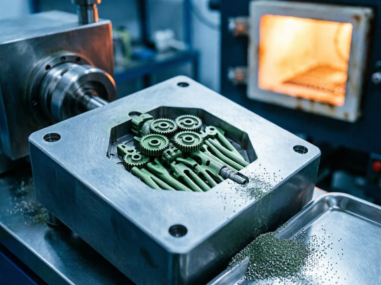
What Is Metal Injection Molding (MIM)? Process Workflow, Suitable Parts, and Key Capability Indicators
Author: Newlife - MIM (新莱福MIM应用工程团队) | Material: | Industry:
What Is Metal Injection Molding (MIM)? Process Workflow, Suitable Parts, and Key Capability Indicators
Application Pain Points: Why Engineers Seek MIM Solutions
Design engineers and procurement teams face a recurring dilemma when specifying small, geometrically complex metal parts: conventional processes force painful trade-offs.
- CNC machining delivers tight tolerances but generates substantial chip waste on intricate geometries, driving per-piece cost higher at elevated production volumes. - Investment casting handles complexity reasonably well but struggles with wall thicknesses below approximately 1.5 mm and often requires secondary machining to meet dimensional specifications. - Conventional powder metallurgy (PM press-and-sinter) is cost-effective for simple shapes yet cannot produce undercuts, cross-holes, or thin-wall features without multi-step tooling. - Stamping and forming are limited to sheet-derived geometries and cannot achieve three-dimensional internal features.
The result: engineers over-specify material, add assembly steps, or accept higher scrap—all of which erode margin. Metal Injection Molding (MIM) was developed precisely to resolve this cluster of constraints by combining the geometric freedom of plastic injection molding with the mechanical performance of wrought metals.
---
Process Comparison Table: MIM vs. Alternative Manufacturing Routes
Criterion | MIM | CNC Machining | Investment Casting | Press-and-Sinter PM |
Part weight range | 0.05 – 200 g (sweet spot < 50 g) | No practical lower limit | 5 g – several kg | 1 – 500 g |
Geometric complexity | Very high (undercuts, micro-features) | High (tool-access dependent) | Moderate–High | Low–Moderate |
Typical tolerance | ±0.3 %–0.5 % of dimension | ±0.01 mm achievable | ±0.5 %–1.0 % | ±0.1 mm (simple) |
Relative density | ≥ 96 %–99 % | 100 % (wrought) | ~100 % | 85 %–92 % |
Material utilization | > 95 % | 20 %–40 % (complex parts) | 80 %–90 % | > 90 % |
Economic volume threshold | 5 k–10 k+ pcs/yr | 1–5 k pcs/yr | 500–5 k pcs/yr | 10 k+ pcs/yr |
Surface finish (as-produced) | Ra 1.0–3.2 µm | Ra 0.4–1.6 µm | Ra 3.2–6.3 µm | Ra 3–8 µm |
Tooling investment | Moderate (injection mold) | None / fixtures | Moderate (wax mold) | Moderate (compaction die) |
Takeaway for decision-makers: MIM occupies the intersection of high complexity, high density, and high volume—where neither machining economics nor casting precision can compete.
---
First-Principles Derivation: The Physics That Govern MIM Outcomes
Principle 1 — Sintering Densification (Driving Force for Near-Net-Shape Density)
The thermodynamic driving force for sintering is the reduction of total surface energy. For a simplified two-sphere model the neck-growth rate can be expressed as:
Where *x* = neck radius, *a* = particle radius, *γ_s* = surface energy, *Ω* = atomic volume, *D* = diffusion coefficient, *T* = absolute temperature, *t* = time, and *B*, *n*, *m* are mechanism-dependent constants.
What this means for your design:
- Finer powder (smaller *a*) accelerates densification; literature consistently shows that fine feedstock enables relative densities ≥ 96 % without hot isostatic pressing. - Higher sintering temperature increases *D* exponentially (Arrhenius dependence), but also increases grain growth and furnace cost. Optimizing the *T–t* envelope is the core process-engineering challenge. - Achieving high density means mechanical properties approach wrought equivalents, reducing the need for large safety factors that inflate part mass and cost.
Principle 2 — Shrinkage Predictability (Dimensional Control)
During sintering the part undergoes isotropic linear shrinkage:
Typical linear shrinkage is 15 %–22 %. Dimensional tolerance is governed by the *uniformity* of green-body density (set during injection) and the *uniformity* of thermal profile in the sintering furnace.
What this means for your design:
- A tolerance of ±0.3 %–0.5 % on final dimensions is reported in the literature when feedstock homogeneity and furnace temperature uniformity are tightly controlled. - Non-uniform wall thickness causes differential shrinkage → distortion. Designing walls within a consistent thickness ratio minimizes this risk. - Gate location and fill-balance simulation during mold design are as critical as in plastic injection—MIM is not "just metallurgy."
---
Design Parameter Recommendations for MIM-Optimized Parts
Parameter | Recommended Range | Rationale |
Wall thickness | 0.3–6 mm (optimal 0.5–3 mm) | Uniform fill, minimal distortion |
Draft angle | 0.5°–1° | Easier ejection, lower mold wear |
Corner radii | ≥ 0.1 mm (internal) | Stress concentration & crack prevention |
Hole diameter (min) | ≥ 0.3 mm | Moldable without core-pin breakage |
Aspect ratio (length : wall) | ≤ 8:1 | Avoids sagging during sintering |
Part mass | 0.05–100 g (ideal < 50 g) | Economic sweet spot vs. machining |
Annual volume | > 5,000 pcs | Amortizes mold tooling |
Tolerance (as-sintered) | ±0.3 %–0.5 % of nominal | Tighter requires secondary finishing |
Optimization strategy: Start with the functional envelope, then iterate wall uniformity and gating with simulation. Target the minimum consistent wall that satisfies load requirements—thinner walls reduce material cost, cycle time, and sintering energy simultaneously.
---
Newlife - MIM Capabilities
Newlife - MIM team supports the critical factors identified above through integrated powder-to-part processing. Fine-particle feedstock enables the high sintered densities described in Principle 1. Full-chain control from mixing through sintering reduces lot-to-lot dimensional variation. Furnace uniformity and process monitoring translate the shrinkage relationship in Principle 2 into production. The same infrastructure accommodates multiple alloy families, allowing engineers to match stainless, iron-based, soft-magnetic, or tungsten-containing materials to application requirements without requalifying entirely separate supply chains.
These capabilities operate under documented quality-management systems.
---
Action Checklist for Engineers Evaluating MIM
1. Audit your current BOM — Identify machined or assembled parts < 50 g with complex geometry; calculate per-piece cost at current and projected volumes. 2. Apply the design guidelines above — Check wall uniformity, aspect ratio, and minimum feature size against MIM-feasible ranges. 3. Estimate density and tolerance requirements — If ≥ 96 % relative density and ±0.5 % tolerance satisfy functional needs, MIM is likely viable without secondary operations. 4. Select candidate material system — Match mechanical, magnetic, or thermal requirements to available MIM alloy families (stainless, iron-based, tungsten, soft magnetic, etc.). 5. Run a cost-volume crossover analysis — Compare MIM tooling amortization + piece price against current process at 10 k, 50 k, and 200 k annual volumes. 6. Contact Newlife - MIM for custom engineering support — Visit [https://www.kingmimpm.com](https://www.kingmimpm.com) to request a DFM consultation, rapid prototyping quote, or material selection review. The Newlife - MIM application engineering team will evaluate part geometry, recommend feedstock and process parameters, and deliver sample parts for validation.
---
References
1. German, R.M. *Metal Injection Molding: A Comprehensive MIM Design Guide*. Metal Powder Industries Federation (MPIF), 2011. 2. German, R.M. *Sintering Theory and Practice*. Wiley-Interscience, 1996. 3. Heaney, D.F. (ed.). *Handbook of Metal Injection Molding*, 2nd Edition. Woodhead Publishing, 2019. 4. MPIF Standard 35 — *Materials Standards for Metal Injection Molded Parts*, 2016 Edition. 5. ISO 22068:2012 — *Sintered Metal Injection Moulded Materials — Specifications*.
---
*Ready to convert complex, high-volume metal parts from machining or casting to MIM? Visit [https://www.kingmimpm.com](https://www.kingmimpm.com) for a feasibility assessment.*