
What Are the Advantages of MIM over Investment Casting and Stamping? Which Scenarios Best Suit Near-Net-Shape Forming?
Published:
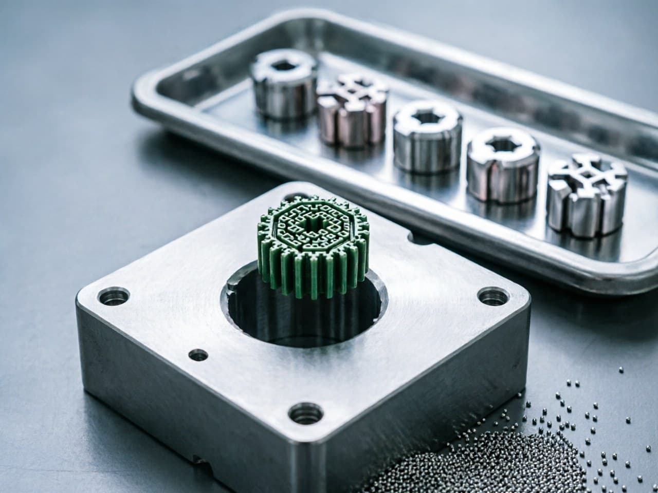
What Are the Advantages of MIM over Investment Casting and Stamping? Which Scenarios Best Suit Near-Net-Shape Forming?
Application Pain Points:
Why Process Selection Matters for Complex Small Parts
Design engineers and procurement teams frequently face a critical decision when specifying metal components with complex geometries, tight tolerances, and moderate-to-high annual volumes: should the part be produced via Metal Injection Molding (MIM), investment casting (IC), or precision stamping?
Each process occupies a distinct envelope defined by part size, geometric complexity, dimensional tolerance, material utilization, and volume economics. Selecting the wrong process can result in:
- Excessive secondary machining costs when tolerances from casting exceed functional requirements. - Tooling amortization penalties when stamping dies are commissioned for geometries that require multiple progressive stations or secondary forming. - Material waste and yield loss when investment casting gates, runners, and risers consume a substantial fraction of the pour weight on small intricate parts. - Design compromise when engineers simplify geometry to accommodate process limitations rather than optimizing for function.
Understanding the theoretical and practical boundaries of each process enables informed decisions that reduce total cost of ownership while preserving design intent.
Near-Net-Shape Process Selection Comparison Table
| Parameter | MIM | Investment Casting | Precision Stamping |
|---|---|---|---|
| Typical part weight | 0.1 – 100 g | 10 g – several kg | 0.5 – 500 g (sheet-based) |
| Wall thickness (min practical) | 0.3 – 0.5 mm | 1.5 – 2.0 mm | Material thickness dependent (≥ 0.1 mm) |
| Geometric complexity | Very high (undercuts, internal channels, micro features) | High (but limited by ceramic core fragility) | Low–moderate (2.5-D, bending, drawing) |
| Achievable tolerance (as-processed) | ± 0.3 % – 0.5 % of nominal | ± 0.5 % – 1.0 % of nominal | ± 0.05 – 0.1 mm (in-plane); springback limits OOP |
| Surface finish (Ra) | 1.0 – 3.2 µm | 3.2 – 6.3 µm | 0.4 – 1.6 µm (blanked face dependent on die condition) |
| Material utilization | > 95 % | 50 – 70 % (gates/risers) | 60 – 85 % (skeleton scrap from strip) |
| Relative density | ≥ 96 – 99 % | ≥ 99 % (fully dense) | 100 % (wrought stock) |
| Tooling cost (indicative) | Medium–high (precision mold) | Low–medium (wax die + ceramic shell) | High (progressive die) |
| Economic volume threshold | 5,000 – 10,000+ pcs/year | 100 – 5,000 pcs/year | 50,000+ pcs/year |
| Material freedom | Wide (stainless, Fe-Ni, W-alloy, soft magnetic, Ti) | Wide (most castable alloys) | Limited to sheet/strip-formable alloys |
| Secondary machining need | Minimal to none | Often required for critical dimensions | Minimal for 2-D features; complex 3-D needs assembly |
Quantitative Model:
Cost Breakeven Analysis — MIM vs. Investment Casting vs. Stamping
A simplified unit-cost model helps engineers identify the volume at which each process becomes economically dominant. The total unit cost C_unit for a given annual quantity Q can be expressed as:
Where: - C_tooling = one-time tooling investment (amortized over n_years, typically 3–5 years) - C_material = raw material cost per part (including scrap/yield factor) - C_process = per-part processing cost (machine time, energy, labor) - C_secondary = post-process machining, deburring, inspection
What this means for design and procurement decisions:
1. MIM has moderate tooling but very low C_secondary because of near-net-shape capability. For complex 3-D parts weighing 0.5–50 g at volumes above approximately 5,000–10,000 parts/year, the tooling amortization becomes negligible relative to the savings in material and machining compared with investment casting.
2. Investment casting carries lower tooling cost, making it attractive for prototypes and low-volume production (hundreds to low thousands). However, C_secondary rises steeply when tolerances tighter than ± 0.5 % are required, because grinding or CNC finishing becomes necessary.
3. Stamping achieves the lowest C_process at very high volumes (> 50,000–100,000/year) for geometries that remain essentially 2.5-D. But once the part requires true 3-D complexity—internal features, variable cross-sections, or multi-material integration—the die complexity (and C_tooling) escalates non-linearly, often making MIM more economical even at high volumes.
Illustrative Breakeven Scenario
For a 5 g stainless-steel component with internal threads, two through-holes, and ± 0.05 mm critical tolerance, relative cost relationships follow the patterns shown in the selection table above. Specific unit-cost figures depend on regional labor rates, alloy pricing, and geometric details.
The model demonstrates that MIM dominates the cost-performance envelope for small, complex, high-tolerance parts at annual volumes from roughly 10,000 to several million pieces.
Design Parameter Recommendations by Process
When to Specify MIM
- Part mass < 100 g, ideally < 50 g - Three-dimensional complexity that would require multi-axis CNC or multi-piece assembly if stamped - Tolerances ± 0.3 – 0.5 % achievable as-sintered, eliminating most secondary operations - Material requires high hardness, corrosion resistance, or magnetic properties not available in sheet form - Annual volume ≥ 5,000 pieces (sweet spot: 50 k – 10 M+)
When Investment Casting Remains Preferable
- Part mass > 100 g or thin-wall castings with large projected area - Low-volume production (< 2,000 pcs/year) where tooling amortization dominates - Alloys that are difficult to sinter (certain superalloys, large-grain-structure requirements)
When Stamping Is Optimal
- Essentially flat or 2.5-D geometry (brackets, contacts, springs, shields) - Ultra-high volume (> 100,000/year) with simple features - Thin-gauge material (0.1 – 3 mm sheet) with in-plane tolerances as the critical dimension
Newlife - MIM Capabilities for Near-Net-Shape Forming
For applications that fall within the MIM-dominant envelope—complex micro-geometry, tight tolerance, medium-to-high volume—Newlife - MIM provides a vertically integrated manufacturing platform:
- High-precision near-net-shape control achieving relative density ≥ 98 % and dimensional tolerances of ± 0.3 – 0.5 %, reducing or eliminating secondary machining that investment casting would require. - Multi-material system production capability spanning stainless steels, iron-based alloys, soft magnetic materials, tungsten-copper, and high-density tungsten alloys—offering material options that stamping simply cannot access from sheet stock. - Scalable flexible manufacturing with monthly capacity exceeding 55 million parts and 20+ sintering furnaces, ensuring that volume ramp-ups do not create delivery bottlenecks that plague investment casting foundries. - Automotive-grade quality system certifications (IATF 16949 / ISO 9001 / ISO 14001) providing the process control documentation and traceability that OEM procurement teams require for safety-critical components.
Action Checklist for Engineers and Procurement Teams
1. Map your part against the selection table above — classify geometry complexity, tolerance class, annual volume, and material. 2. Calculate breakeven volume using the unit-cost model; if your part sits in the 5,000–5,000,000 range with 3-D complexity, MIM likely offers the lowest total cost. 3. Identify tolerance-critical features — if as-cast tolerances from IC require secondary machining on > 2 features, MIM's as-sintered precision will yield significant per-part savings. 4. Evaluate material requirements — if your application demands alloys unavailable in sheet/strip form (W-alloy, soft magnetic Fe-Ni, 17-4PH at high hardness), MIM unlocks material options that stamping cannot. 5. Request a DFM (Design-for-Manufacturability) review early in the design cycle to optimize wall thickness, draft, and feature placement for MIM-specific shrinkage compensation. 6. Contact Newlife - MIM application engineering team for a feasibility assessment, cost comparison, and prototype timeline.
References
1. German, R.M. Metal Injection Molding: A Comprehensive MIM Design Guide. Metal Powder Industries Federation (MPIF), 2011. 2. Heaney, D.F. (Ed.). Handbook of Metal Injection Molding, 2nd Edition. Woodhead Publishing, 2019. 3. Beeley, P. Foundry Technology, 2nd Edition. Butterworth-Heinemann, 2001. 4. ASM International. ASM Handbook, Volume 15: Casting. ASM International, 2008. 5. Boljanovic, V. Sheet Metal Forming Processes and Die Design. Industrial Press, 2004. 6. MPIF Standard 35. Materials Standards for Metal Injection Molded Parts. Metal Powder Industries Federation, 2016.
<!-- JSON-LD: {"@context": "https://schema.org", "@type": "TechArticle", "headline": "What Are the Advantages of MIM over Investment Casting and Stamping? Which Scenarios Best Suit Near-Net-Shape Forming?", "inLanguage": ["en", "zh"], "keywords": "MIM vs investment casting vs stamping advantages, near-net-shape manufacturing process comparison, metal injection molding precision casting selection, MIM complex geometry small parts production, near-net-shape forming cost breakeven analysis", "about": [{"@type": "Thing", "name": ""}, {"@type": "Thing", "name": ""}], "author": {"@type": "Organization", "name": "Newlife - MIM", "alternateName": "新莱福MIM应用工程团队"}, "publisher": {"@type": "Organization", "name": "Newlife - MIM", "url": "https://www.kingmimpm.com"}} -->