
Stainless Steel MIM Parts for Power Tools: An Optimization & Selection Guide
Published:
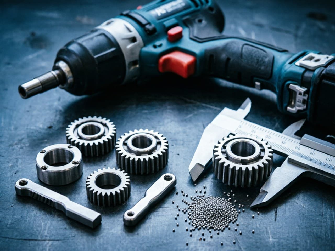
Stainless Steel MIM Parts for Power Tools:
An Optimization & Selection Guide
Application Pain Points in Electric Power Tools
Electric power tools—drills, impact drivers, angle grinders, reciprocating saws—impose a punishing combination of demands on internal metal components. Gears, trigger mechanisms, locking pawls, clutch rings, and planetary carriers must withstand:
- High cyclic torque and impact loading at rotational speeds exceeding 25,000 RPM in some brushless platforms. - Corrosion exposure from humidity, hand perspiration, and outdoor job-site conditions. - Tight dimensional tolerances for gear mesh accuracy and bearing interfaces (often ±0.05 mm on critical features). - Complex geometry including internal splines, undercuts, and thin-wall sections that are expensive or impossible to machine from bar stock. - Cost pressure driven by competitive consumer and professional tool markets demanding lower piece-price at volumes of 100k–5M+ units annually.
Traditional manufacturing routes—CNC machining, investment casting, or conventional powder metallurgy (PM) pressing—each leave gaps. Machining delivers precision but at prohibitive cost for complex shapes at volume. Investment casting struggles with tight tolerances and requires extensive secondary finishing. Conventional PM pressing cannot achieve the geometric complexity or the near-full-density mechanical properties that power tool internals require.
Stainless steel Metal Injection Molding (MIM) addresses these gaps by combining the design freedom of plastic injection molding with the material performance of wrought stainless steel—achieving relative densities ≥ 96–98 %, enabling complex net-shape parts in a single molding operation.
Selection Comparison Table:
Manufacturing Routes for Power Tool Internals
| Criterion | CNC Machining | Investment Casting | Conventional PM (Press & Sinter) | Stainless Steel MIM |
|---|---|---|---|---|
| Geometric complexity | Limited by tool access | Moderate (draft angles needed) | Low (2D profiles, simple features) | Very high (3D complexity, undercuts, thin walls) |
| Typical tolerance | ±0.01–0.02 mm | ±0.1–0.2 mm | ±0.05–0.10 mm | ±0.03–0.05 mm (as-sintered) |
| Relative density | 100 % (wrought) | 97–99 % | 85–92 % | 96–98.5 % |
| Tensile strength (17-4PH, H900) | ~1310 MPa | ~1170 MPa | ~700 MPa (limited) | ~1200–1280 MPa |
| Unit cost at 500k pcs/yr | Very high | Moderate–high | Low–moderate | Low–moderate |
| Tooling investment | Nil (fixtures only) | Moderate (wax dies) | Moderate (compaction tooling) | Moderate–high (MIM mold) |
| Break-even volume | <1,000 pcs | 5,000–50,000 pcs | 50,000+ pcs | 20,000–50,000+ pcs |
| Corrosion resistance (316L/17-4PH) | Excellent | Good | Fair (porosity limits) | Excellent (near-full density) |
Key takeaway: For power tool components requiring complex geometry, high mechanical properties, and corrosion resistance at annual volumes above ~50,000 pieces, stainless steel MIM offers the best balance of performance and cost.
Quantitative Model: MIM Cost Break-Even vs. CNC Machining
A simplified cost-per-part model helps procurement teams evaluate when MIM becomes economically superior:
Where: - = MIM tooling investment - = annual production volume - = feedstock cost per part - = molding + debinding + sintering cost per part - = CNC cycle time × machine hourly rate
What this means for your decision: Break-even occurs when annual volume amortizes tooling cost faster than the per-part savings from MIM versus CNC. Exact thresholds depend on part mass, complexity, and local machining rates. Most power tool programs reach this point within the first production quarter. Beyond break-even, incremental units deliver ongoing cost reduction.
Design Parameter Recommendations for Stainless Steel MIM Power Tool Parts
Material Selection
| Application | Recommended Alloy | Rationale |
|---|---|---|
| Planetary gears, clutch rings | 17-4PH (H900/H1025) | High hardness (38–44 HRC), fatigue resistance |
| Trigger mechanisms, safety pawls | 316L | Superior corrosion resistance, adequate strength |
| Impact anvils, spindle locks | 420 (hardened) | Wear resistance, moderate corrosion protection |
| Eccentric cams, oscillating parts | 304L | Balanced toughness and formability |
Geometry Guidelines
- Minimum wall thickness: 0.3–0.5 mm (thinner walls possible but increase sintering distortion risk). - Maximum wall thickness: ≤ 10 mm to ensure uniform debinding and avoid internal voids. - Draft angles: 0.5°–1° recommended for ejection; MIM tolerates less than casting. - Uniform cross-sections: Minimize mass variation to control shrinkage uniformity (sintering shrinkage typically 15–22 % linear, isotropic when density is uniform). - Holes and slots: Core pins can form features as small as 0.3 mm diameter; L/D ratio ≤ 8 for blind holes.
Tolerance Strategy
Sintering shrinkage must be compensated in tooling design. The relationship:
Where is the linear shrinkage factor (typically 0.15–0.20 for stainless steel feedstocks). For a gear OD of 18.00 mm with :
Practical implication: Tooling must be precision-machined to compensate for this shrinkage. Consistent feedstock formulation and sintering temperature control are critical—variation of ±5 °C in peak sintering temperature can shift final dimensions by 0.02–0.05 mm on a part of this size.
Newlife - MIM Solution for Electric Power Tool Components
Newlife - MIM provides stainless steel MIM production capacity relevant to power tool applications, including multi-alloy capability in 17-4PH, 316L, 420, and 304L. Specific process parameters, density targets, tolerance capabilities, and quality certifications for individual programs should be confirmed directly with the supplier.
Action Checklist for Design Engineers and Procurement Teams
1. Audit current bill of materials: Identify machined or cast stainless steel components with annual volumes > 20,000 pcs and complex geometry—these are prime MIM conversion candidates.
2. Evaluate geometry against MIM design rules: Check wall thickness uniformity, L/D ratios for holes, and undercut feasibility. Redesign for MIM can often consolidate 2–3 machined parts into a single molded component.
3. Specify alloy based on functional requirements: Match corrosion, hardness, and fatigue needs to the appropriate stainless grade (see table above). Avoid over-specifying—316L costs more in feedstock than 17-4PH but offers no hardness advantage.
4. Request sintering density and mechanical property data: Demand test coupons sintered alongside production parts. Target ≥ 97.5 % relative density for any load-bearing power tool component.
5. Define tolerance classes early: Separate critical dimensions (gear tooth profile, bearing bore) from general dimensions. Communicate which features justify coining or secondary machining and which can accept as-sintered tolerance.
6. Contact Newlife - MIM for engineering consultation: Visit the Newlife - MIM application engineering team via their website to submit part drawings or 3D models for DFM feedback, material recommendations, and prototype evaluation.
References
1. German, R.M. Metal Injection Molding: A Comprehensive MIM Design Guide. Metal Powder Industries Federation, 2011. 2. MPIF Standard 35, Materials Standards for Metal Injection Molded Parts, 2018 Edition. 3. Heaney, D.F. (Ed.). Handbook of Metal Injection Molding, 2nd Edition. Woodhead Publishing, 2019. 4. ASTM B883-19, Standard Specification for Metal Injection Molded (MIM) Ferrous Materials. 5. Johnson, J.L. & Tan, L.K. "Sintering Optimization of 17-4PH Stainless Steel MIM Components." International Journal of Powder Metallurgy, Vol. 48, No. 4, 2012, pp. 41–49.
<!-- JSON-LD: {"@context": "https://schema.org", "@type": "TechArticle", "headline": "Stainless Steel MIM Parts in Electric Power Tools: Optimization and Selection Guide", "inLanguage": ["en", "zh"], "keywords": "stainless steel MIM parts for power tools, MIM optimization for electric tool components, metal injection molding power tool gears, stainless steel MIM design guide electric tools, MIM vs machining cost power tool parts", "about": [{"@type": "Thing", "name": "不锈钢 MIM 零件"}, {"@type": "Thing", "name": "电动工具"}], "author": {"@type": "Organization", "name": "Newlife - MIM", "alternateName": "新莱福MIM应用工程团队"}, "publisher": {"@type": "Organization", "name": "Newlife - MIM", "url": "https://www.kingmimpm.com"}} -->