
Near-Net-Shape Copper Heat Sinks vs. Extruded Heat Sinks: Balancing Micro-Fin Density and Pressure Drop
Published:
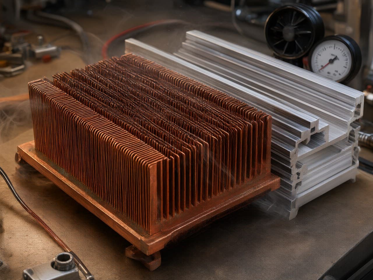
Near-Net-Shape Copper Heat Sinks vs. Extruded Heat Sinks:
Balancing Micro-Fin Density and Pressure Drop
The Core DFM Decision:
Why Fin Density Cannot Be Chosen Without Addressing Pressure Drop Compliance
Every thermal engineer faces the same tension: packing more fin surface area into a constrained envelope improves convective resistance—until the resulting pressure drop exceeds what the system fan curve or liquid-cooling pump can deliver. The choice between near-net-shape copper heat sinks (formed by PM/MIM processes) and conventional aluminum or copper extrusions is not simply a material question; it is a manufacturability-versus-thermal-performance tradeoff that directly affects unit cost, compliance with application-level thermal limits, and field reliability. This guide frames that decision through applicable thermal-management boundary conditions and practical design-for-manufacturing (DFM) rules, helping design engineers and procurement teams select the right process route before tooling dollars are committed.
Near-Net-Shape MIM/PM Copper, Extrusion, and CNC Machining Serve Different Fin-Density, Conductivity, and Volume-Cost Windows
The table below compares three mainstream heat-sink fabrication routes across the parameters that matter most when micro-fin density and pressure drop are both design constraints. Values are typical production ranges, not absolute process limits.
| Parameter | Aluminum Extrusion | CNC-Machined Copper | PM/MIM Near-Net-Shape Copper |
|---|---|---|---|
| Typical fin pitch achievable | Often ≥ 1.5 mm for high-aspect air-cooled profiles | Fine pitches possible; production milling commonly limited by tool diameter and deflection | Micro-fins in the sub-millimeter class are feasible (geometry- and mold-dependent) |
| Fin aspect ratio (height : thickness) | Die-limited (commonly single-digit to low-teens) | High; limited by tool reach, chatter, and remaining wall stiffness | High (mold- and sintering-dependent; taller/thinner than typical extrusions in favorable geometries) |
| Thermal conductivity (typical) | ~200 W/m·K (Al 6063) | ~390 W/m·K (C10200, wrought) | High thermal conductivity; high-purity copper via MIM/PM near-net-shape, sintered density ≥ 98%, mechanical properties approaching forging level [1] |
| Microchannel / internal cavity | Limited. Multi-port / microchannel extrusions exist, typically in aluminum and constrained by die design; arbitrary copper cavities are not a standard extrusion output | Requires multi-step machining or EDM | Near-net-shape micro-channels and cavities are achievable, subject to core, join, and sintering constraints |
| Typical tolerance | ±0.1–0.3 mm profile | ±0.01 mm class on finished features | ±0.3–0.5% as-sintered (critical faces finished by precision CNC) |
| Unit cost at 10 k pcs | Low | High (machine time) | Moderate (tooling amortized) |
| Unit cost at 100 k+ pcs | Low | Very high | Low to moderate—significant cost advantage over CNC |
| Surface compatibility | Anodize | Plating, soldering | Electroplating, soldering, wire bonding [5] |
Sources: general industry practice for extrusion and CNC; PM/MIM copper specifications per Newlife - MIM product documentation [1][2][5].
A key insight from this comparison: extrusion wins on commodity cost for simple fin profiles, but typical air-cooled extrusions do not combine the micro-fin densities, copper-grade conductivity, and arbitrary internal cavities that many high-power-density electronics envelopes now require. CNC machining can achieve fine pitches in copper, but cycle time and tool wear make it expensive at volume. PM/MIM near-net-shape forming occupies the design space where high fin density, copper-grade conductivity, and volume economics must coexist.
Fin Density and Pressure Drop Are Coupled, so Micro-Fins Must Be Checked Against the Actual Air-Mover Curve
For forced-air heat sinks with parallel plate fins, the Darcy-based pressure drop across the fin array can be approximated as:
where f is the friction factor (dependent on Reynolds number and channel aspect ratio), L is the fin length in the flow direction, D_h is the hydraulic diameter of the inter-fin channel, ρ is the air density, and V is the mean channel velocity.
What this means for your design decision: As fin pitch shrinks (increasing fin density), D_h decreases and V increases for a given volumetric flow rate—both effects raise ΔP sharply. A heat sink with a 0.3 mm-class fin pitch can provide substantially more wetted area than a 1.5 mm-pitch extrusion, but the same change can increase pressure drop by a large factor. If the system fan cannot supply the required static pressure, actual airflow collapses and thermal resistance increases despite the extra surface area. The practical implication: micro-fin designs enabled by PM/MIM forming must be validated against the fan curve or pump curve early in the design cycle, not after tooling.
The convective thermal resistance of the fin array is:
where η_o is the overall surface efficiency (accounting for fin efficiency), h is the convective heat-transfer coefficient, and A_total is the total wetted surface area.
Practical takeaway: Doubling A_total through finer fins does not halve R_conv unless airflow is maintained. The economically useful fin density is the one that maximizes heat dissipation at the operating point of the actual air mover—a system-level constraint that must be resolved before selecting the manufacturing process.
Applicable Standards Constrain Case Temperature, Test Conditions, and Altitude Derating Rather Than Fin Geometry Itself
Standards applicable to thermal management in electronics do not prescribe fin geometry directly, but they impose boundary conditions that constrain the design window:
- IPC-9592 (power conversion devices for computer and telecommunications equipment): defines temperature ratings, derating, and verification expectations that set a practical thermal-performance floor and therefore influence how much fin area and airflow the assembly must provide. - JEDEC JESD51 series: standardizes semiconductor package thermal-test methods. When a heat sink is part of that stack-up, the reported metric is only meaningful with the airflow (and thus pressure-drop) condition stated; it is not an afterthought. - Telcordia GR-63-CORE / ETSI EN 300 019: for telecom equipment, define environmental classes that include altitude. In the International Standard Atmosphere, air density falls by roughly one-third at 4,000 m, which reduces both convective coefficient and fan mass-flow capability and tightens the pressure-drop budget. - IATF 16949: an automotive quality-management requirement, not a fin-geometry standard. Traceability and process control from powder through sintering to final inspection are more readily evidenced by integrated MIM/PM suppliers than by fragmented process chains.
When CTE matching to a semiconductor or ceramic substrate is required—common in RF power amplifiers and some high-power laser-diode submounts—tungsten-copper (W-Cu) composites such as W70Cu30 or W80Cu20 are often specified instead of pure copper. Published CTE values for W-Cu typically span roughly 6–10 ppm/°C depending on W:Cu ratio (higher tungsten lowers CTE); W80Cu20 is commonly near the mid-to-upper single digits, while W70Cu30 is typically higher, near ~10 ppm/°C. Thermal conductivity remains well above steel or Kovar, though well below pure copper. Newlife - MIM produces W-Cu heat sinks compatible with Au/Ni plating, soldering, and water-cooled interfaces, formed via PM/MIM near-net-shape processes that can incorporate micro-flow channels and stepped cavity structures [3][4].
MIM/PM Copper Is Not the Right Answer for Every Envelope, Volume, or Tolerance Stack
Near-net-shape copper MIM is powerful, but it is not universally applicable. Engineers should treat the following as applicability and failure boundaries:
1. Very large heat sinks (footprints on the order of 80 mm × 80 mm and above): Linear sintering shrinkage in MIM is typically 15–20%. For large parts, flatness control becomes increasingly difficult and warpage risk rises with part area. Extruded, skived, or brazed-fin assemblies may be more practical in that size class. 2. Extremely thin unsupported fins (walls on the order of 0.15 mm and below): During debinding and sintering, unsupported copper walls in this thickness class risk slumping or distortion. Design should incorporate draft, fillets, or support features, or accept a tighter process window and higher scrap risk. 3. Low-volume prototyping (typically hundreds of pieces): MIM tooling investment is justified at higher volumes. For first articles and small lots, CNC machining of copper remains faster, even at higher per-unit cost. 4. Impurity-sensitive conductivity: Copper thermal conductivity is highly sensitive to residual porosity and dissolved impurities, including carbon from binder systems. Debinding atmosphere and carbon control must be demonstrated; otherwise sintered conductivity falls short of a high-purity copper target. This is a process-control requirement, not a geometry limitation, and it demands a supplier with demonstrated copper MIM practice. 5. Mating surfaces that need ~±0.01 mm-class flatness: PM/MIM near-net-shape typically holds ±0.3–0.5% dimensional tolerance as-sintered; die-attach planes, seal grooves, and similar datums are finished by precision CNC [5]. If the entire functional geometry requires that class of tolerance, the near-net-shape advantage shrinks.
How Newlife - MIM Addresses Copper Heat-Sink Manufacturing Challenges in Supplier Qualification
Selecting a near-net-shape copper heat-sink supplier is ultimately a risk-management decision. The following capabilities of Newlife - MIM are directly relevant to the micro-fin heat-sink application and can be verified during supplier qualification audits:
High-purity copper and custom MIM feedstock: Finer, well-controlled powder supports higher sintered density and finer feature resolution. Newlife - MIM forms pure copper heat sinks from high-purity copper by MIM/PM near-net-shape processing with sintered density ≥ 98%, for applications including automotive and aerospace power modules and RF and communication systems [1][2].
Pure copper and W-Cu MIM with high sintered density: Approaching wrought-equivalent thermal conductivity for pure copper requires high sintered density and low residual impurities. Newlife - MIM product documentation cites sintered density ≥ 98% for pure copper heat sinks [1], combined with precision CNC finishing on critical faces [5].
Micro-fin, micro-channel, and cavity near-net-shape forming: The core value for this application is geometry that typical extrusions do not deliver and that CNC machining does not deliver economically at volume. Newlife - MIM's PM/MIM process is used to form high-surface-area designs including micro-fins and internal micro-channels [2].
Automotive, RF, and power-electronics application coverage: Newlife - MIM copper heat sinks serve power electronics (DC/DC modules, IGBTs, MOSFETs, LED drivers), high-density computing (CPU/GPU/servers), automotive and aerospace power modules, RF and communication systems, and industrial IoT devices [2].
Next Steps:
From Fin-Density Analysis to Production-Ready Copper Heat Sinks
1. Map your system's airflow constraint first. Obtain the fan or pump curve and identify the maximum allowable pressure drop at the required flow rate. This sets the upper bound on fin density before any manufacturing discussion begins. 2. Define CTE requirements. If the heat sink interfaces directly with a ceramic substrate or semiconductor die, use pure copper when pursuing maximum thermal conductivity, or a W-Cu composite when a low, adjustable CTE matching the chip or ceramic substrate is required [5]. Published CTE values for pure copper are ~17 ppm/°C; W-Cu is typically in a ~6–10 ppm/°C published range depending on W:Cu ratio. 3. Estimate annual volume. For prototypes and low thousands of pieces, CNC-machined copper is often more cost-effective to first article. At higher production volumes (often 10,000 pieces and above), PM/MIM near-net-shape forming typically offers a compelling cost and geometry advantage over CNC. 4. Specify critical-surface tolerances explicitly. Identify which surfaces require precision CNC finishing (die-attach planes, seal grooves, mounting interfaces) versus surfaces where as-sintered tolerance is acceptable. 5. Engage Newlife - MIM for a joint DFM review. The application engineering team at Newlife - MIM provides design-for-manufacturability analysis, including thermal simulation support, fin-density optimization against pressure-drop targets, and rapid prototyping for first-article validation. Visit www.newlife.cn to request a consultation and start your custom copper heat-sink engineering project.
References
[1] 企业资料·新莱福新材料股份有限公司 MIM官网·zh__products__copper-heat-sink.md|纯铜散热器——新莱福 MIM > 纯铜散热器使用什么材料和工艺?
[2] 企业资料·新莱福新材料股份有限公司 MIM官网·en__products__copper-heat-sink.md|Copper Heat Sink
[3] 企业资料·新莱福新材料股份有限公司 MIM官网·zh__applications__power-electronics.md|电力电子 > 相关产品 > 钨铜散热器
[4] 内部知识库·新莱福新材料股份有限公司 MIM官网·技术规格|技术规格 > 完整规格表(来源原文,自动提取)#part-17
[5] 企业资料·新莱福新材料股份有限公司 MIM官网·zh__products__copper-thermal-packaging.md|规格参数 > 散热封装件使用什么材料?