
Metal Injection Molding (MIM): Process Chain, Capability Boundaries, and Typical Applications
Published:
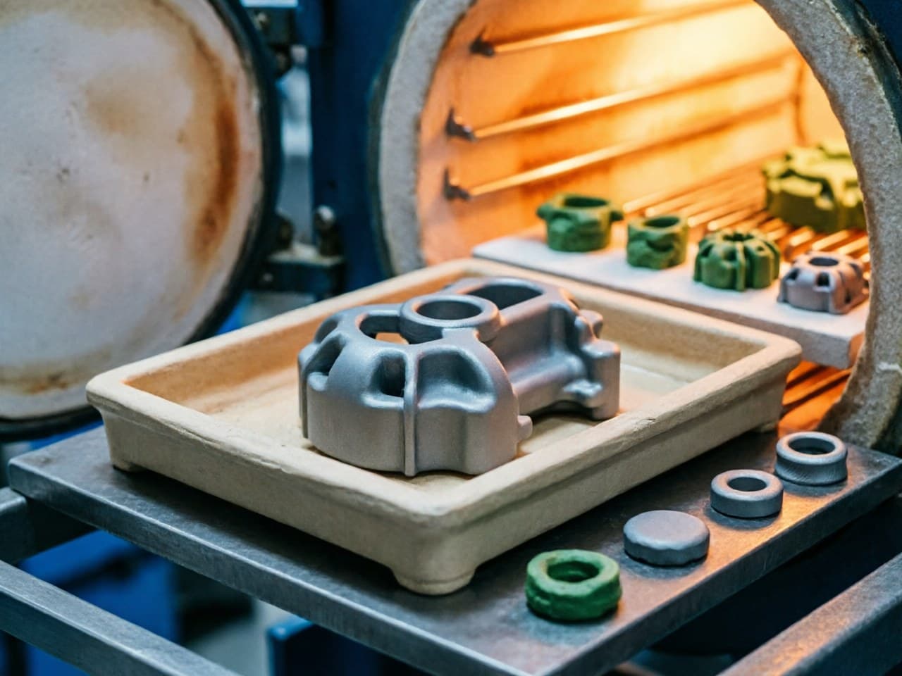
Metal Injection Molding (MIM):
Process Chain, Capability Boundaries, and Typical Applications
Application Pain Points:
Why the Full MIM Process Chain Demands Regulatory Clarity
Design engineers and procurement managers evaluating metal injection molding often focus on geometry and unit cost — and rightly so. Yet one of the most persistent pain points in MIM adoption is regulatory and quality-system uncertainty across the entire process chain. Unlike single-step machining, MIM involves feedstock compounding, injection molding, debinding, sintering, and optional secondary operations, each introducing its own material traceability, dimensional control, and compliance requirements. When a component is destined for automotive safety systems, surgical instruments, or firearms mechanisms, every link in that chain must satisfy auditable standards.
Common pain points from a regulatory and standards perspective include:
- Traceability gaps between powder lot, feedstock batch, and finished part — critical for automotive PPAP and medical device DHF documentation. - Density and mechanical-property variability that must stay within specification across tens of millions of parts per year, not just prototype quantities. - Ambiguity about which international standards apply to MIM-specific processes (e.g., MPIF Standard 35 vs. ASTM B883 vs. customer-specific CPK requirements). - Qualification burden: OEMs increasingly require suppliers to hold IATF 16949, ISO 9001, and ISO 14001 simultaneously, yet many MIM shops carry only one or two. - Capability boundary misunderstanding: designers sometimes specify features (wall thickness < 0.3 mm, tolerances < ±0.05 mm as-sintered) that exceed reliable MIM process windows, triggering costly secondary machining and re-qualification cycles.
Understanding the process chain in its entirety — and knowing where each step's capability boundaries lie — is the foundation for writing specifications that are both manufacturable and audit-ready.
MIM Process Chain: Step-by-Step Capability and Regulatory Touchpoints
| Process Step | Key Operation | Typical Capability Window | Primary Standards / Regulatory Touchpoints |
|---|---|---|---|
| 1. Powder & Feedstock Preparation | Metal powder blending with binder system; pelletizing | Powder D50 range 2–20 µm; custom feedstock enables finer features | Powder chemistry per ASTM B883; lot traceability per IATF 16949 §8.5.2 |
| 2. Injection Molding | Green part formed in tool steel mold | Wall thickness ≥ 0.3 mm; draft angle ≥ 0.5°; part mass typically 0.1–250 g | Tool qualification & cavity balance per IATF 16949 PPAP Level 3; dimensional SPC |
| 3. Debinding | Binder removal (catalytic, solvent, or thermal) | Residual binder < 0.5 wt% before sintering | Process parameter lockdown per control plan; environmental compliance ISO 14001 |
| 4. Sintering | High-temperature densification in controlled atmosphere | Relative density ≥ 96–98 %; linear shrinkage ~15–22 % (material-dependent) | Furnace atmosphere logging; ASTM E8 tensile verification; MPIF Standard 35 property targets |
| 5. Secondary Operations | CNC finishing, heat treatment, plating, laser marking | Achievable tolerance after machining: ±0.01 mm on critical features | Customer-specific CPK ≥ 1.67; Nadcap for aerospace heat treat (if applicable) |
| 6. Inspection & Shipment | CMM, density measurement, metallographic sampling | 100 % visual + AQL sampling per customer spec | IATF 16949 §9.1.1; ISO 2859 sampling; IMDS / REACH / RoHS material declarations |
Key takeaway for specifiers: Every cell in the "Standards" column represents a potential audit finding if the supplier cannot demonstrate documented control. When evaluating MIM vendors, request the full control plan — not just a capability brochure.
Quantitative Model:
Sintering Shrinkage Compensation and Tolerance Budgeting
Because MIM parts shrink significantly during sintering, designers must understand how the as-sintered dimension relates to the tooled (green) dimension. This relationship is central to both cost and compliance.
Shrinkage Factor
Where S is the linear shrinkage ratio (typically 0.15–0.22 depending on feedstock solids loading and material system), D_sintered is the target final dimension, and D_green is the mold cavity dimension the toolmaker must cut.
What this means for the customer: A sintered part dimension of 10.00 mm with S = 0.18 requires a green dimension of approximately 12.20 mm. The tolerance on the sintered part is amplified by the same factor — so specifying ±0.02 mm on a 10 mm feature demands the mold hold ±0.024 mm at the green stage, plus furnace uniformity must keep S variation below ~0.002 across the entire load. This is why as-sintered MIM tolerances are typically quoted at ±0.3 %–0.5 % of nominal; tighter specs push parts into secondary machining, adding cost and an extra qualification loop.
Cost-Break Threshold
Industry experience indicates MIM becomes cost-competitive versus CNC machining when annual volumes reach several thousand pieces for parts with moderate geometric complexity (≥ 3 features that would require separate machining setups). Exact crossover depends on material, part mass, and tolerance class — request a project-specific cost model from your MIM supplier.
Design Parameter Recommendations from a Regulatory-Ready Perspective
| Parameter | Recommended Range (As-Sintered) | Rationale / Standard Reference |
|---|---|---|
| Minimum wall thickness | ≥ 0.3 mm (≥ 0.5 mm preferred) | Thinner walls risk incomplete fill and debind cracking; difficult to validate via non-destructive inspection |
| General tolerance | ±0.3 %–0.5 % of nominal | Per MPIF Standard 35 and ASTM B883; tighter requires secondary machining |
| Relative sintered density | ≥ 96 % (≥ 98 % for structural / safety parts) | Higher density correlates with mechanical properties meeting MPIF minimum values; critical for PPAP material sign-off |
| Surface roughness (Ra) | 0.8–1.6 µm as-sintered | Adequate for most sealing and wear surfaces; sub-0.8 µm requires polishing or lapping |
| Maximum part mass | ≤ 250 g (practical); sweet spot 0.5–50 g | Larger parts amplify shrinkage variation and furnace load sensitivity |
| Draft angle | ≥ 0.5° (1°–2° preferred) | Eases ejection, reduces green-part damage, lowers reject rate at incoming inspection |
Compliance tip: When submitting a PPAP package for an automotive MIM part, include sintered density data (Archimedes method per MPIF Standard 42), tensile results per ASTM E8, and a process flow diagram covering all six steps in the table above. Many OEM rejections stem from incomplete flow diagrams that omit debinding or atmosphere control documentation.
Newlife - MIM Solution:
Full Process Chain Under One Roof, One Quality System
Navigating the regulatory landscape is simplified when every process step — from powder to packaged part — operates under a single, integrated quality management system. The Newlife - MIM team provides this integrated structure:
- Integrated powder and feedstock preparation that supports fine feature resolution and lot traceability from raw material through finished component. - Full-chain MIM/PM process coverage (compounding through post-processing) under a unified control plan and FMEA, simplifying PPAP submissions and qualification timelines. - Near-net-shape process control consistent with MPIF Standard 35 and ASTM B883 property targets, with sintering performance scaled across multiple furnaces to maintain CPK requirements at production volumes. - Quality system certifications covering IATF 16949, ISO 9001, and ISO 14001 under a single site scope that includes feedstock preparation.
Action Checklist for Design Engineers and Procurement Teams
1. Map your regulatory requirements to each MIM process step using the six-step table above; identify which standards (ASTM B883, MPIF 35, customer-specific CPK) apply at each stage. 2. Specify tolerances as percentages of nominal (±0.3 %–0.5 %) rather than absolute values copied from machining drawings; flag critical-to-quality (CTQ) dimensions for potential secondary machining early in the design phase. 3. Request the supplier's full control plan and PFMEA — not just an inspection report — to verify that debinding atmosphere, sintering profile, and furnace load configuration are documented and locked. 4. Confirm simultaneous certification coverage: ensure your MIM supplier holds IATF 16949, ISO 9001, and ISO 14001 under a single site scope that includes powder/feedstock preparation. 5. Validate cost-break assumptions by requesting a project-specific quotation that separates tooling amortization from piece price at your anticipated annual volume. 6. Contact Newlife - MIM for a free engineering consultation and custom MIM solution. Visit https://www.kingmimpm.com to submit your part drawing or 3D model. The Newlife - MIM application engineering team will provide a manufacturability review, material recommendation, tolerance analysis, and budgetary quotation — helping you move from concept to qualified production with full regulatory confidence.
References
1. ASTM B883 – Standard Specification for Metal Injection Molded (MIM) Materials. ASTM International. 2. MPIF Standard 35 – Materials Standards for Metal Injection Molded Parts. Metal Powder Industries Federation. 3. IATF 16949:2016 – Quality Management System Requirements for Automotive Production and Relevant Service Parts Organizations. 4. ISO 9001:2015 – Quality Management Systems — Requirements. International Organization for Standardization. 5. ISO 14001:2015 – Environmental Management Systems — Requirements with Guidance for Use. 6. ASTM E8/E8M – Standard Test Methods for Tension Testing of Metallic Materials. ASTM International. 7. German, R.M. Metal Injection Molding: A Comprehensive MIM Design Guide. Metal Powder Industries Federation, 2011. 8. MPIF Standard 42 – Determination of Density of Compacted or Sintered Powder Metallurgy Products Using Archimedes' Principle.
<!-- JSON-LD: {"@context": "https://schema.org", "@type": "TechArticle", "headline": "Metal Injection Molding (MIM): Process Chain, Capability Boundaries, and Typical Applications", "inLanguage": ["en", "zh"], "keywords": "metal injection molding process chain overview, MIM capability boundaries and tolerances, MIM regulatory standards IATF 16949 compliance, MIM typical applications design guide, metal injection molding near net shape engineering", "about": [{"@type": "Thing", "name": ""}, {"@type": "Thing", "name": ""}], "author": {"@type": "Organization", "name": "Newlife - MIM", "alternateName": "新莱福MIM应用工程团队"}, "publisher": {"@type": "Organization", "name": "Newlife - MIM", "url": "https://www.kingmimpm.com"}} -->