
MIM Near-Net-Shape Forming for Optical Module Housings and Thermal Management Parts: Which Machining Operations Can Be Eliminated?
Published:
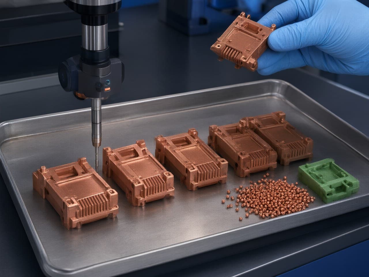
MIM Near-Net-Shape Forming for Optical Module Housings and Thermal Management Parts: Which Machining Operations Can Be Eliminated?
An optical module housing is a deceptively expensive part. It is small, thin-walled, pocketed, bossed, and usually made from a copper alloy chosen for thermal conductivity — which is exactly the material class that is least pleasant to cut. Its companion heat spreader is worse: a finned or channelled copper plate where most of the stock removal produces chips rather than function.
Near-net-shape metal injection molding (MIM) does not remove machining as a category. It removes a specific class of operations — the roughing class, whose only job is to walk a billet toward a shape that already looks like the finished part — and leaves behind a short list of high-value finishing cuts. Knowing exactly which cuts migrate into the tool and which stay on the mill is the whole decision.
The cost problem in an optical module housing is machining time, not the copper
In a machined copper housing, cycle time is dominated by the operation list, not by the copper invoice alone: saw the billet, face it, rough the cavity, semi-finish, finish the walls, mill the outer step, mill or skive the fin array, drill and tap, deburr, then plate. On a pocketed, thin-walled housing a large share of the billet becomes chips that must be recovered and re-melted. The buy-to-fly ratio should be calculated from the actual blank mass and finished mass of the part in hand; no generic percentage is used here.
Three secondary costs ride along: repeated re-fixturing (each setup is a datum error and a handling step), tool wear in gummy copper alloys, and hand deburring — a labour step that scales with part count and is difficult to hold to a Cpk. The practical question is therefore not "MIM or CNC" in the abstract, but which of these operations needs to exist at all.
Near-net-shape MIM removes roughing, fin milling and deburring, and keeps only the datum cuts
For a typical housing, the operations that disappear when the pocket, the outer step, the bosses and the fin field are all formed in the tool are:
- Cavity roughing and semi-finishing — the largest single block of cycle time. - Fin array milling or skiving — fins, micro-fins and micro-channels are shaped by the tool, not by a cutter path, provided the field can be filled, drafted and ejected. - Boss, standoff and mounting-pad machining — moulded directly with the body. - Outer profile and step milling — the cavity defines the profile that a mill would otherwise walk; a parting-line witness can remain. - Deburring of internal pockets — no interrupted cutter at the pocket floor, so the machining burr at that floor is avoided. - Repeated re-fixturing between roughing operations — one near-net part replaces several intermediate setups. - Bulk chip making from the housing blank — machining chip volume falls sharply. Runners, gates and process scrap remain and belong in the utilisation estimate.
What stays on the mill is a short, low-stock-removal list: datum faces, the lid land or sealing surface where flatness matters, precision bores such as the fibre receptacle, threads and tapped holes, and occasionally a lap or grind. Parting-line flash, a gate vestige or an ejector witness may still need a light deflash or edge break; that is not the same operation as pocket-floor deburring, and it should stay on the routing until a sample shows otherwise. Plating, if the finish spec requires it, is unchanged by the forming route. The remaining cuts are finishing cuts with small stock — cheap relative to a roughing cycle, and far easier to hold than a stock-removal sequence. That is the real economy: MIM does not delete machining, it shrinks it from a stock-removal problem into a dimensional-control problem.
A route-and-binder comparison shows where each process stops paying
The table below compares the realistic forming routes for a small copper housing or heat spreader. It is a decision aid, not a ranking — the better route flips with volume, wall thickness and flatness requirements.
| Route | Formed in the tool | Machining removed | Machining still required | Constraint to qualify |
|---|---|---|---|---|
| CNC from copper billet | Nothing — every feature is a cut | — | All of it | Cycle time and buy-to-fly on complex, thin-wall geometry |
| Skived fins + soldered base | Fin array only | Fin milling | Base machining, joining, flatness of the joint | A second component and a joint are introduced; joint thermal performance and reliability must be qualified |
| Die-cast Al/Zn + plating | Housing shell | Pocketing, profile | Bore, threads, plating prep | The alloy is not copper; conductivity, soundness and plating must be qualified against the spec |
| MIM near-net (Cu / Cu alloy / W-Cu) | Pocket, fins, micro-channels, bosses, profile (as-sintered near-net) | Roughing, fin milling, bosses, pocket-floor deburring, repeated roughing setups | Datum faces, sealing land, precision bores, threads; possible light deflash | Tooling amortization; shrinkage measured on the production lot; moldable aspect ratio and flatness |
| Stamped laminate stack | 2.5D profile per layer | 2D profile cutting | Stacking, bonding; true 3D features are outside the route | Blind 3D cavities are not a stacked-sheet geometry |
Binder chemistry matters as much as the forming route when the part is copper, because debinding and sintering jointly determine residual carbon, oxygen pickup and final dimensions. The notes below are process constraints to confirm with the feedstock supplier, not measured results for a named compound.
| Binder family | Debinding route | Implication for copper parts | Constraint to verify with the supplier |
|---|---|---|---|
| Wax / polyolefin | Thermal, slow ramp | A common thermal route; carbon residue and oxidation are not automatically acceptable on copper | Ramp versus section thickness; cracking; residual carbon on the actual section |
| PEG / water-soluble | Solvent or water, then thermal removal of the backbone | The soluble fraction is removed before backbone burnout; residual carbon still depends on the backbone and the thermal cycle | Green-part dimensional stability; bath control; backbone residue |
| POM / catalytic | Acid vapour | Acid vapour can attack copper; compatibility must be demonstrated on the alloy, not assumed from the binder name | Atmosphere compatibility; furnace cleanliness; surface and carbon/oxygen result on the actual part |
| Multi-component / proprietary | Two-stage | Shrinkage is feedstock-specific | Shrinkage data from the actual feedstock lot, by axis |
The break-even count and shrinkage arithmetic decide the route before any quote arrives
Two relations frame the routing argument before a supplier is locked in. They do not themselves produce a crossover count: the costs and the shrinkage have to be quoted and measured. Assumed unit costs are not a substitute for that input.
1. Break-even volume. MIM carries tooling; CNC carries hours.
N* = C_tool / (U_CNC − U_MIM)
where C_tool is mould and development cost to be amortized, and U_CNC and U_MIM are unit costs at the same finished specification. Dimensions: currency divided by currency per piece gives a piece count. The relation assumes U_CNC > U_MIM, treats both unit costs as comparable at the volume in question, and ignores the time value of money, learning and logistics. U_MIM must include remaining machining, any required plating, yield loss and secondary operations — not the as-sintered price alone. Insert the programme's own quotes and compare N* with the risk-adjusted forecast. Do not judge the tooling line item by itself, and do not import a universal crossover count.
2. Shrinkage compensation. The tool is not the part. Under an isotropic linear shrinkage assumption,
L_die = L_part / (1 − S)
with S the linear sintering shrinkage as a fraction, not as a percent. If a supplier quotes 15%, the value that enters the formula is 0.15, not 15. Real shrinkage is often anisotropic (flow direction versus transverse); the scalar formula is a first estimate. Production die compensation should use measured shrink factors by axis from the production feedstock lot.
Algebraic example only — not a Newlife - MIM feedstock coefficient and not a measured part. A 30.00 mm finished dimension at S = 0.15 requires L_die = 30 / 0.85 = 35.29 mm. Two sensitivities must not be mixed:
- Required die size, at the tool-design stage: dL_die/dS = L_part / (1 − S)^2 = 30 / 0.85^2 ≈ 41.5 mm per unit of S. An error of 0.1 percentage point (ΔS = 0.001, not 0.1) moves the die dimension by about 42 µm. - Finished length, once that die is cut: |ΔL_part| ≈ L_die × |ΔS| ≈ 35 µm for the same 0.1 percentage point.
A ±0.3% band on 30.00 mm is ±90 µm. A finished-length shift of about 35 µm from a 0.1 percentage-point shrinkage error is a substantial fraction of that one-sided allowance. That is why a general as-sintered tolerance in the ±0.3–0.5% class — the general-dimension band stated for this process — should not be asked to cover every callout, and why the tight surfaces should be reserved for post-sinter finishing. Ask for shrinkage by axis, and for Cpk on the designated critical dimensions, from the production feedstock lot, not from a generic datasheet.
The design window is set by wall thickness, aspect ratio and which surfaces must stay flat
MIM's freedom comes from the mould, so the DFM conversation is about the mould, not the machine. Uniform walls avoid the differential shrinkage that shows up as sink on a lid land; abrupt thick-to-thin transitions are where debinding and sintering stress concentrates. Fin and micro-channel fields are an aspect-ratio, draft and ejection problem: keep fin height modest relative to fin thickness, include draft, and confirm the actual limit against the specific tool rather than a generic chart. A molded fin is not a geometric copy of a skived rectangular fin; the thermal model should use the section the tool can eject. Radii instead of sharp internal corners, draft on every wall that must eject, and gate placement away from sealing surfaces (to keep weld lines out of the leak-critical zone) are the recurring corrections.
The productive habit is to divide dimensions into two buckets on the drawing: formed in the tool (pockets, fins, bosses, profile, mounting pads) and finished after sintering (datums, sealing land, bores, threads). Leave a defined machining allowance on the second bucket. The allowance is part- and process-specific; set it from measured shrinkage and the finishing method, and the two processes stop competing and start cooperating. Where the drawing is dominated by many ultra-tight callouts rather than by complex geometry, CNC is often still the cheaper route. MIM's advantage is the geometry that would otherwise be roughed away, not a tight tolerance on every feature.
MIM is the wrong answer when thin fins, large flat planes or small volumes dominate the cost
The failure modes worth stating plainly, because a mis-scoped MIM project costs more than a conservative CNC one, are process boundaries — not a catalogue of measured scrap rates:
- Debinding and sintering cracks at abrupt changes in section thickness. A thick boss on a thin wall is a risk to design out or to prove in a trial, not a feature to assume will survive. - Fin and micro-channel aspect ratio. Molded fins need draft and must eject and survive debinding. A knife-edged, very high aspect-ratio field that only skiving can produce does not automatically leave the routing; confirm moldability before deleting fin milling. - Carbon and oxygen control. Copper is oxidation-prone, and binder residue affects the sintered result. Atmosphere and cycle must be controlled, and the outcome verified on the actual part, not inferred from the alloy name. - Do not infer thermal conductivity from sintered density or from the alloy family name. Density and chemistry are necessary controls. Conductivity, flatness after plating, and fin-field performance are part-level results to measure or otherwise qualify. - Shrinkage dispersion on long dimensions. Arithmetic of the stated general tolerance, not a measured part: at ±0.3–0.5%, a 60 mm span carries ±180–300 µm. Anything tighter belongs in post-machining. - Distortion of large thin planes. Flatness on a wide lid land or a thin fin field can drift through sintering. If flatness is the governing requirement, plan a finishing operation from the start. - Tooling versus prototype quantity. A production tool is justified by volume and by geometry that machining cannot cheaply repeat. Prototypes and one-off samples should be costed on a mill, or as a scoped rapid sample, rather than assumed to carry a production tool. Rapid sampling is a separate route from a multi-cavity production tool and should be quoted as such. - Very thick sections and large envelopes lengthen the sinter cycle and complicate density uniformity.
If two or more of those apply, the honest recommendation is a hybrid: machine the prototype, then convert only the high-volume, geometry-heavy variant to MIM — and cost that split explicitly.
Auditable evidence beats a capability brochure:
powder, feedstock, Cpk and traceability
Because the routing benefit depends on shrinkage discipline, the process chain should be inspectable rather than asserted. Newlife - MIM's copper and tungsten-copper MIM route is relevant here on four points a design or sourcing engineer can audit against the stated capability:
- Powder and feedstock are in-house. Self-developed ultrafine copper, iron and nickel powders at D50 ≤ 3 µm, plus custom MIM feedstock. Shrinkage can be managed against a known powder and mix history rather than treated as an unknown imported feedstock; lot traceability should still be requested on the quote. - Copper thermal hardware is a stated production route. Pure copper, copper alloy and tungsten-copper MIM parts with sintered density ≥ 8.4 g/cm³, with micro-fins, micro-channels and cavities formed near-net — the geometry class that would otherwise be milled from billet. - Dimensional capability is stated as a general band, and it is measurable. Relative density ≥ 98% and general tolerances of ±0.3–0.5%. Datum faces, sealing lands, precision bores and threads remain post-sinter operations. Post-processing is part of the stated process chain; the quote should say which of those cuts are included so the tolerance chain is explicit. - The quality-system certifications are the audit frame. IATF 16949, ISO 9001 and ISO 14001. Ask for the Cpk on the designated critical dimensions of this part, not a catalogue value.
Send one housing drawing and one heat-spreader drawing for a route-by-route comparison
The decision is cheap to make if it is made with real numbers. What to prepare:
1. A 2D drawing that separates tool-formed dimensions from post-machined dimensions, with the finished stock allowance marked. 2. Annual and lifetime volumes per variant, so the break-even count can be calculated against the CNC alternative rather than against a list price. 3. The thermal requirement — fin field, channel width, base thickness — so the mould concept and the sintering cycle are evaluated together, including draft and ejection. 4. The flatness and bore callouts that genuinely cannot be relaxed; these define what stays on the mill. 5. A prototype quantity, so the hybrid path (machine or rapid-sample first, production tool second) can be costed honestly.
Then visit http://www.newlife.cn and contact Newlife - MIM for a consultation: send the housing and heat-spreader drawings and the target volumes, and the Newlife - MIM application engineering team will return a route-by-route comparison — which machining operations the tool removes, which operations remain, and an engineering proposal built around the dimensional and thermal requirements.
References
1. MPIF Standard 35, Materials Standards for Metal Injection Molded Parts, Metal Powder Industries Federation. 2. ISO 22068:2012, Sintered metal injection moulded materials — Specifications, International Organization for Standardization. 3. German, R. M. and Bose, A., Injection Molding of Metals and Ceramics, Metal Powder Industries Federation, 1997. 4. German, R. M., Powder Metallurgy and Particulate Materials Processing, Metal Powder Industries Federation, 2005. 5. ASM Handbook, Volume 7: Powder Metal Technologies and Applications, ASM International, 1998. 6. Newlife - MIM, process and product information, http://www.newlife.cn.