
How Much IACS Conductivity Can Copper MIM Parts Retain? The Mechanisms by Which Density and Grain Size Matter
Published:
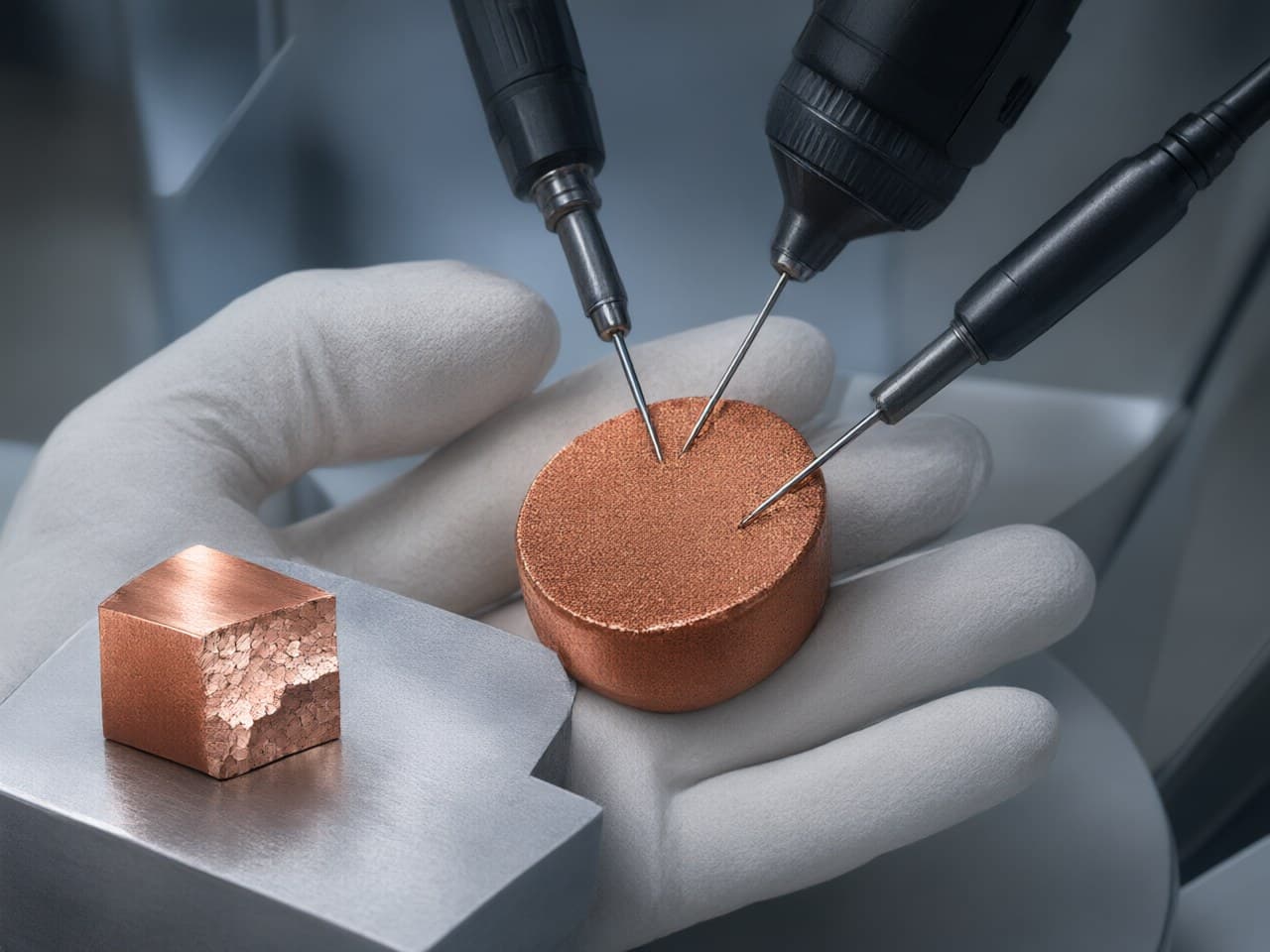
How Much IACS Conductivity Can Copper MIM Parts Retain? The Mechanisms by Which Density and Grain Size Matter
A compact current-carrying heat spreader is a useful way into this question. The part spreads heat away from a power amplifier, carries the DC feed, and has to hold mating faces flat enough to be soldered or bolted. It also has integral bosses, a fin field and a stepped perimeter. The first instinct is often CNC-milled pure copper. The second is copper MIM, because those features consume spindle time. The argument that nearly kills the MIM option is conductivity: what happens to the annealed-copper IACS reference when the copper is sintered rather than machined?
A copper MIM part can keep most of the conductivity of the copper between the pores if relative density and purity are both controlled. It should not be treated as equivalent to annealed wrought copper. The first-order losses are residual porosity and solute or interstitial contamination. Grain-boundary scattering is a distant third at the grain sizes ordinary sintering leaves. Knowing which of those losses the drawing is actually paying for is what separates a sound DFM decision from an expensive one.
The First DFM Question on a Copper MIM Part Is Not Geometry but How Many IACS Points the Design Can Afford to Lose
A copper MIM program is decided at the DFM review, where an electrical target and a cost target meet on the same wall sections. Conductivity targets push toward fully dense, clean, high-purity copper. Cost targets push toward the near-net shape that takes machining off integral fins, bosses and mounting features.
Those goals conflict only when the conductivity window has no room for porosity, or when the geometry is too simple to justify a mold. They do not conflict merely because the part is copper. Published near-net control for this route is a relative density of at least 98% and a dimensional tolerance of ±0.3–0.5%. That density sits close to wrought copper. The cost difference, where it exists, is the features that no longer have to be cut. A part whose conductivity tolerance is wafer-thin and whose geometry is simple remains a CNC or extrusion part, not a MIM part. Complex, low-mass hardware — optical-module parts, packaging heat spreaders, switch contacts, electrodes — is the class of geometry where that trade is worth running. Pure copper and tungsten–copper MIM parts are already used for 5G optical modules, electronic packaging thermal management, switch contacts and electrodes.
Choosing the Copper MIM Material Is Really Choosing Which Loss Mechanism You Can Live With
For a given cross-section, the material family sets the conductivity ceiling. Process tuning does not lift a part above the alloy it was molded from.
| Material family | What it buys | What it costs | Where it is used |
|---|---|---|---|
| Pure copper | Highest electrical and thermal conductivity in the family | Lowest strength; large thin flats sag if unsupported in sinter | Heat spreaders, electrodes, current paths |
| Bronze | Higher strength and wear resistance than pure copper | Conductivity materially below pure copper; the penalty depends on the alloy, not on the family name | Contacts and wear-resistant current-carrying parts |
| Brass | Moderate conductivity with useful corrosion resistance | Conductivity below pure copper; again alloy-specific | Connector bodies, hardware, fittings |
| Tungsten–copper | CTE can be tailored toward semiconductor and ceramic packages; thermal-shock resistance, platability and weldability | Much lower conductivity than pure copper; higher mass | RF and optoelectronic heat sinks, thermal spreaders, micro-channel spreaders |
Bronze and brass in that table are alloy families, not catalog grades with a single IACS value. Conductivity inside each family moves enough that the designation has to be specified before anyone quotes a loss.
If the constraint is "carry the current and avoid machining the features," stay with pure copper and spend the design margin on section, not on hope. If the constraint is surviving repeated thermal cycles without cracking a die attach, tungsten–copper can be the right answer even though conductivity is given up — the part is then a thermal-stress component, not a bus. Making that trade at material selection is worth more than downstream process tuning.
The route comparison that matters is the same trade, without invented scores for the alternatives:
| Decision | Lean away from copper MIM | Lean toward copper MIM |
|---|---|---|
| Geometry | Simple, thick, few integral features | Integral fins, bosses, steps, channels; small mass |
| Conductivity band | Essentially no allowance below the wrought reference | The section can absorb the loss allowed by the density and purity specification |
| Density need | Must remain at wrought density | Relative density of at least 98% is acceptable |
| Starting form | Extruded bar, wrought plate, or flat sheet | A molded three-dimensional net shape |
Read geometry and the conductivity band together. Near-net copper MIM exists to form micro-fins, micro-channels and cavities that would otherwise be machined, while holding the published relative density. A simple thick conductor does not need that route. A flat, high-volume terminal with no real third dimension usually does not either. Selection is that trade. It is not a universal ranking of processes.
Binder chemistry matters because it sets how cleanly the part debinds. Residual carbon becomes porosity or contamination, and both sit on the first-order side of the IACS loss:
| Binder approach (industry-general) | Debinding route | Tendency on defect risk | Where it fits |
|---|---|---|---|
| Wax–polymer | Thermal plus solvent | Longer cycles; higher risk on thick sections | Simple, thick-wall geometries |
| POM-based / catalytic | Acid vapor plus thermal | Low residue; good dimensional stability | Thin walls, tight-tolerance parts |
| Water-soluble / PEG-based | Water immersion plus thermal | Low residue; humidity-sensitive feedstock | Environmentally constrained programs |
| Multi-component with backbone polymer | Solvent plus thermal | Good shape retention | Parts where distortion is the main risk |
The table is generic industry practice, not a plant recipe. The molder owns the choice, and it has to be validated on the geometry rather than assumed from a brochure.
Two Cited Models Bound the Density and Grain-Size Losses; They Do Not Replace a Conductivity Measurement
Both mechanisms are established. Neither one is a substitute for a measurement on the finished part, and neither one captures impurity scattering.
Porosity. Treating residual pores as a dilute dispersion of insulating spheres, Maxwell's result (often called Maxwell–Eucken in the porous-materials literature) gives
σ_eff / σ₀ ≈ (1 − P) / (1 + P/2)
where P is the pore volume fraction and σ₀ is the conductivity of the solid between the pores, not automatically 100% IACS.
Two published figures must not be folded into one porosity. The copper, copper-alloy and tungsten–copper family is published at a sintered density of at least 8.4 g/cm³. Near-net control is published at a relative density of at least 98%. Dividing 8.4 g/cm³ by the theoretical density of pure copper (8.96 g/cm³) is not a valid porosity for this discussion. That division is about 94% relative density, which contradicts the relative-density floor, and it is meaningless for copper alloys and tungsten–copper, whose theoretical densities are not 8.96 g/cm³. For pure copper the two figures are consistent in the other direction: 98% of 8.96 g/cm³ is 8.78 g/cm³, which is above the 8.4 g/cm³ absolute floor. The floor is not the density to insert into the porosity model.
The porosity that belongs in the model is the one implied by the relative-density specification. At the published floor, P = 0.02, and the equation returns σ_eff / σ₀ ≈ 0.97. That is an optimistic bound on the porosity term alone, under the assumption of isolated spherical pores. It is not a measured IACS value and not a quotation. Connected or irregular pores retain less. If the solid copper itself is below the annealed reference, % IACS is lower again.
Near full density the same relation falls by about 1.5% of matrix conductivity for each additional 1% of porosity. Real sintering pores cost more than that spherical-pore slope. In copper, thermal conductivity tracks electrical conductivity, so the same porosity term is also a heat-spreading loss on a spreader. The practical translation is not a promised IACS number. A purchasing specification should state a minimum relative density and require a per-lot density result, rather than accept a generic "high density" claim, and it should still require a conductivity measurement.
Grain boundaries. The Mayadas–Shatzkes model treats grain boundaries as partially reflecting planes:
α = (λ / d) · R / (1 − R), with ρ_g / ρ₀ = [3(1/3 − α/2 + α² − α³ ln(1 + 1/α))]⁻¹
where λ is the electron mean free path, d is the grain size, and R is the boundary reflection coefficient. For copper near room temperature, λ is about 39 nm in this class of model. R is not a universal constant and is not assumed here.
The scaling is what selection needs. α is proportional to λ/d. Grains left by ordinary sintering are micrometres across, orders of magnitude above λ, so α stays small unless the grain size is driven toward the mean free path. Keep a micrometre-scale sintered grain structure if conductivity matters. Finer grains can buy strength. They do not buy IACS, and the conductivity cost rises once grain size approaches λ. Do not chase sub-micron grains in the name of conductivity.
Put side by side, the DFM conclusion is narrower than a single retained-IACS figure. At a relative density of at least 98%, porosity is the density lever that belongs in the review, and it is a few percent of matrix conductivity only in the optimistic spherical-pore bound — more if the pores are connected. Grain size is not that lever unless the process is being pushed toward the mean free path. Purity is first-order as well, and neither equation above contains it.
The Design Window Closes Quickly on Wall Thickness, Aspect Ratio and Distortion
Copper is forgiving on many sections and unforgiving on thin, large, unsupported ones. High thermal expansion and low strength near sintering temperature mean a broad fin field warps unless the ribs are ganged, the aspect ratio is kept modest, and the part is supported through the sinter cycle. Micro-fins, micro-channels and cavities are within the published near-net capability. They still have to be designed so the supports and the section transitions are credible. Validate distortion on the actual footprint. Do not treat a generic wall-thickness slogan as a process window.
Set tolerances from the published band, which is ±0.3–0.5% of the dimension. On a 30 mm feature that is ±0.09–0.15 mm by arithmetic, not a second, tighter capability. If a mating face is toleranced inside the sinter band, do not fight the furnace. Leave machining stock on that face only, and let the MIM process deliver the rest net. That split usually keeps most of the near-net cost advantage and makes the tight face achievable on the first tool. Size the current-carrying section so the conductivity reduction allowed by the density and purity specification is absorbed in the design, rather than discovered at qualification.
When Copper MIM Is the Wrong Answer:
Debinding Cracks, Carbon Control and Conductivity Ceilings
Some copper parts should not be quoted as MIM. A useful review says so before the tool is cut.
- Thick-to-thin transitions crack in debinding. Binder leaves through connected pore channels that sintering later closes. Abrupt section changes trap that transport and concentrate stress. Taper the transition or change the design. - Residual carbon becomes porosity. Binder that is not fully removed can react with copper oxide and generate CO/CO₂, leaving voids where the current has to flow. Copper wants a clean, low-dew-point reducing atmosphere. A cycle qualified on stainless steel is not automatically qualified on copper. - Solute contamination is disproportionate. Iron, phosphorus, chromium and silicon are strong electron scatterers in copper. Pickup from furnace furniture, setters or powder handling can move conductivity by more than the concentration on a certificate would suggest. It will not show on the drawing. It will show in the measurement. - Large, simple, thick conductors are the wrong quote. Extruded bar plus limited CNC keeps both cost and conductivity. So does stamping, for small flat terminals with no third dimension. - A specification written only for oxygen-free wrought copper is the wrong quote. MIM is not a route to the conductivity of the best oxygen-free high-conductivity wrought copper. No supplier should imply that a sintered part will satisfy a window written exclusively around that material. There is also no basis for promising a result above the annealed-copper reference from sintering alone.
The boundary is straightforward. MIM fits when complexity per unit mass is high, the features would otherwise be machined, and the acceptable IACS band has room for the porosity and purity the process will actually deliver. It loses when the part is simple, thick, or held to a conductivity window that leaves no room for pores or tramp solutes.
What a Purchasing Team Can Actually Audit Before Awarding a Copper MIM Program
Audit evidence, not brochures. For a conductive copper part, four records carry most of the risk: a per-lot density result, a conductivity result on the finished part (ASTM B193 is the usual resistivity method; IEC 60028 defines the annealed-copper reference), dimensional capability on the critical features, and powder-lot traceability behind the feedstock. A density certificate does not uniquely determine IACS once pore shape and purity vary, which is why the conductivity result has to be on the list.
Newlife - MIM runs the full chain in-house — mixing, granulating, injection, debinding, sintering and post-processing — so a conductivity question can be traced to a feedstock lot rather than stopping at a supplier boundary. Powder is developed internally, including ultrafine copper, iron and nickel powders and custom MIM feedstock with D50 ≤ 3 µm, so particle-size distribution, oxygen and lot history are known quantities rather than incoming unknowns. Pure copper, copper-alloy and tungsten–copper MIM is published at a sintered density of at least 8.4 g/cm³, with near-net forming of micro-fins, micro-channels and cavities where the alternative is machining the copper. Separately, near-net process control is published at a relative density of at least 98% and a tolerance of ±0.3–0.5%. Absolute density and relative density are not interchangeable across that family, because theoretical density depends on composition; the IACS argument for pure copper uses relative density. The quality system is certified to IATF 16949, ISO 9001 and ISO 14001, so density and conductivity plans, calibration and change control are auditable. Certification of the system is not the same thing as a PPAP on a particular heat spreader.
Two questions are worth asking any copper MIM supplier, including Newlife - MIM. Which atmosphere and carbon specification apply to this alloy? What is the capability on the current-carrying cross-section? The answers should come with numbers from the part, not from a brochure.
The Next Step Is to Send Us the Drawing Together with the IACS Target
Density, not grain size, decides the outcome for most copper MIM parts, and only against a specific geometry, alloy and atmosphere. Purity can overturn a density-only estimate. Neither lever is a number to assume from the process name.
Send the drawing, the current rating, the thermal requirement and the acceptable IACS band to the Newlife - MIM application engineering team. The review covers wall thickness and distortion risk, a route recommendation across pure copper, copper alloys such as bronze or brass, and tungsten–copper, and a density and conductivity expectation stated for that geometry — plus rapid prototyping to check it before tooling. Visit http://www.newlife.cn to start a free consultation and discuss a custom engineering solution for the copper MIM program.
References
1. ASTM B193, Standard Test Method for Resistivity of Electrical Conductor Materials, ASTM International. 2. IEC 60028, International Standard of Resistance for Copper, International Electrotechnical Commission (definition of the International Annealed Copper Standard). 3. G. Mayadas and M. Shatzkes, "Electrical-resistivity model for polycrystalline films: the case of arbitrary reflection at external surfaces," Physical Review B 1, 1382 (1970). 4. J. C. Maxwell, A Treatise on Electricity and Magnetism, Clarendon Press, 1873 (effective conductivity of a dilute dispersion of spheres). 5. R. M. German, Powder Metallurgy and Particulate Materials Processing, Metal Powder Industries Federation, 2005. 6. ASTM B962, Standard Test Methods for Density of Compacted or Sintered Powder Metallurgy (PM) Products Using Archimedes' Principle, ASTM International. 7. MPIF Standard 35, Materials Standards for PM Structural Parts, Metal Powder Industries Federation. 8. IATF 16949:2016, Quality Management System Requirements for Automotive Production and Relevant Service Parts Organizations.