
How Does MIM Vacuum Sintering Affect Relative Density — and How to Consistently Achieve 98%+?
Published:
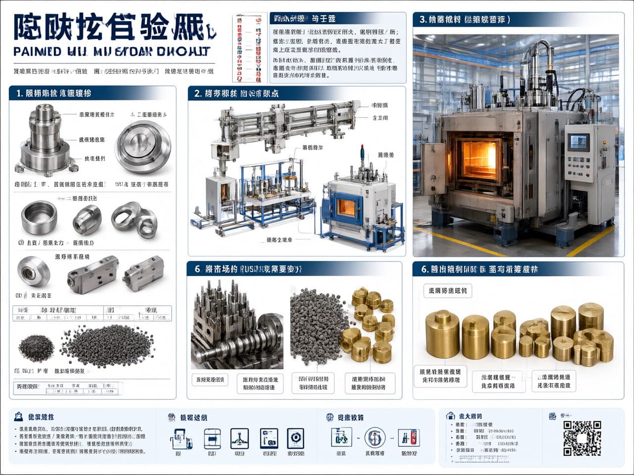
How Does MIM Vacuum Sintering Affect Relative Density — and How to Consistently Achieve 98%+?
Why Your Target Relative Density in MIM Sintering Dictates the Entire Cost Chain
In metal injection molding (MIM), relative density is not only a QC number. It anchors the DFM (design for manufacturability) tree: furnace class, atmosphere route, hold time, post-processing, and piece cost all move when the density target moves from a mid-96% class part to a 98%+ class part.
A common early-project error is to freeze geometry first and then “fit” sintering afterward. The more reliable sequence is reverse design: start from the required mechanical function (strength, hardness, fatigue, leak tightness), infer the minimum relative density that can support that function, and treat that density as a constraint on the sintering path.
Key cost-decision nodes (directional, plant-specific; quote-level deltas to be verified):
| Decision | Relative density in the ≤96% class | Relative density in the 96–98% class | Relative density in the ≥98% class |
|---|---|---|---|
| Typical furnace class | Continuous belt furnaces often cover this band | Pusher furnaces or batch vacuum furnaces | Batch high-vacuum furnaces; high-purity hydrogen batch furnaces are an alternative on some alloys |
| Typical atmosphere | H₂/N₂ mixed atmospheres | High-purity H₂ or low vacuum | High vacuum with partial-pressure Ar backfill at peak temperature |
| Hold / profile | Shorter high-temperature hold | Moderate hold | Longer hold with stepped heating |
| Post-processing | HIP more often required if pores remain open or leak paths persist | Application-dependent | HIP can often be avoided when the duty is not fatigue- or leak-critical; “wrought-equivalent” claims must be proven on the actual alloy and heat treat |
| Piece-cost tendency | Baseline sinter cost | Higher capital and cycle time | Higher sinter cost that may still be lower than sinter + HIP if density and closed-pore quality are already sufficient |
Engineering takeaway: Vacuum sintering is not automatically cheaper or more expensive. Its extra cycle and furnace cost is justified when it raises closed-pore quality enough to drop HIP, or when oxide reduction and alloy cleanliness cannot be secured in a mixed-gas continuous furnace. Cost deltas are plant- and load-specific and should be quoted, not assumed.
Comparing MIM Binder Systems and Sintering Processes Reveals Which Route Best Supports High Relative Density After Vacuum Sintering
The binder system sets residual carbon after debinding and the open-pore network that remains in the brown part. Both control whether vacuum sintering can still vent gas while pores close, and whether the last increment of densification is blocked by CO bubbles or trapped insoluble gas.
| Comparison | Wax-based / wax–polymer systems | Catalytic debinding (POM-based) | Water-soluble binder systems |
|---|---|---|---|
| Residual carbon after debinding | Often higher and more variable; literature-typical lots fall roughly in the 0.03–0.08 wt% band (to be verified on the feedstock) | Typically lower when catalysis is complete; literature-typical lots fall roughly in the 0.01–0.04 wt% band (to be verified) | Sensitive to incomplete extraction and drying; residual carbon can run higher than catalytic routes (to be verified) |
| Open-pore connectivity after debinding | Moderate; depends on wax extraction path | Generally favorable: a fine interconnected pore network if catalytic removal is uniform | Can leave locally closed or skin-restricted paths if drying/extraction is uneven |
| Vacuum-sinter compatibility | Usable, but binder vapor can condense in cold zones | Generally the cleanest vacuum-furnace fit among common MIM binders | Requires a controlled drying / pre-sinter outgas stage so water vapor does not load the vacuum system |
| Density tendency after a well-run vacuum sinter | Commonly reaches the high-96% to ~98% class on thin, well-debound stainless parts | Most often the first choice when 98%+ is a hard target | Can reach high density, but is less forgiving on thick sections and carbon-sensitive stainless grades |
| Furnace contamination risk | Wax vapor deposition increases cold-zone cleaning and batch-to-batch drift | Lower organic load if catalysis is complete | Water vapor and incomplete dry-out are the main vacuum-system risks |
| Typical material fit | Broad (stainless, low-alloy steels, Fe–Ni) | Broad; often preferred when residual carbon and furnace cleanliness are critical | Used on stainless and other systems, but process windows are feedstock-specific—not “stainless only” |
What actually decides 98%+:
1. Residual carbon. Under vacuum, leftover carbon can reduce oxides and leave as CO/CO₂—useful in a narrow window, harmful if excess carbon remains after pores close. Trapped CO is a common reason a part stalls in the high-96% to 97% band. For 316L-class stainless, leftover carbon is also a corrosion-spec problem, not only a density problem. Catalytic POM systems are often chosen because they make that carbon window easier to hit—not because vacuum “requires” POM.
2. Open-pore connectivity. Densification in the intermediate stage still needs an escape path for gas. A uniform interconnected brown-part pore network delays isolation of pores and gives vacuum pumping more time to work. Local skins, thick cores, or collapsed extraction paths close pores too early.
3. Furnace cleanliness. Wax-rich systems increase condensate on shields and pumping lines. That does not make wax binders unusable; it does mean more maintenance and a higher risk of carbon or vapor contamination drifting from load to load.
Vacuum Sintering Temperature Profiles, Vacuum Levels, and Atmosphere Must Work Together to Push MIM Density Beyond 98%
Vacuum sintering can raise the density ceiling versus mixed-gas continuous sintering, but only when oxide reduction, pore-gas removal, and evaporation control are sequenced on purpose. It is not a single “high vacuum” trick.
Mechanism 1: Surface-oxide reduction (not simple thermal decomposition)
MIM powders are typically in the ~5–20 μm class, so native oxide films occupy a large surface area and block early metal–metal contact. High vacuum lowers oxygen partial pressure. Residual carbon from powder and binder can then reduce surface oxides, with CO/CO₂ pumped out of the retort. Hydrogen atmospheres reduce oxides by a different path; vacuum is not the only reducing route.
For 316L-class stainless, Cr-rich oxides are relatively stable. Reduction depends on temperature, carbon activity, and pO₂, not on a single decomposition temperature. If carbon is too low, oxides persist and necks form late. If carbon is too high, CO is generated after pores close and density stalls. That carbon–oxide window is the real 97% → 98% bottleneck.
Mechanism 2: Pore-gas escape before isolation
In H₂/N₂ sintering, N₂ that is insoluble in the matrix can be trapped when pores close and then oppose capillary shrinkage. Vacuum lowers the gas pressure inside still-open pores and removes the mixed-gas reservoir. This advantage disappears if pores close while a backfill gas is already present at too high a pressure, or if debinding left closed cores.
Mechanism 3: Stepped heating plus partial-pressure Ar at peak temperature
A production cycle that consistently aims at 98%+ is a temperature–vacuum–gas program, not a peak-temperature setpoint. The table below is a typical 316L-class industrial window, not a universal recipe. 17-4PH, Fe–Ni, and liquid-phase heavy alloys use different peaks, holds, and atmospheres.
``` Stage Temperature Ramp Vacuum / gas Purpose
Preheat / outgas RT → ~600°C ~3–5°C/min rough to ~10⁻¹ Pa class Moisture and residual binder leave while pores are still open Mid-temp hold ~600°C → ~1050°C ~5°C/min ~10⁻² Pa class Oxide reduction begins; continue pumping CO/CO₂ High-T densify ~1050°C → ~1350°C ~3°C/min ~10⁻³ Pa class Main solid-state densification window for 316L-class parts Peak hold ~1350–1380°C 2–4 h typical 10⁻³ Pa class + Ar backfill Closed-pore shrinkage; limit Cr/Mn evaporation Cooling peak → RT furnace or Ar Ar backfill to ~10⁴ Pa class Control cooling rate and distortion ```
Process detail that is often missed: A modest Ar partial pressure at peak hold—commonly in the 500–2000 Pa class for stainless—is used to slow evaporation of Cr and Mn. Pure high vacuum at 1350°C+ can deplete the surface, hurt local densification, and degrade corrosion resistance. Backfill too early or too high, and Ar itself becomes the trapped-gas problem the vacuum cycle was meant to avoid.
Hot-zone uniformity, load size, setter contact, and pumping speed are as important as the written recipe. A thin-wall coupon at 98.5% does not prove a dense load of heavier parts.
Wall Thickness, Mass, and Geometry Complexity Constrain the Achievable Sintered Density Even When the Furnace Cycle Is Sound
A correct vacuum cycle cannot outrun brown-part transport limits. Geometry sets the practical density ceiling.
Wall-thickness effects (engineering tendency, not a guaranteed density map):
| Wall thickness | Vacuum-sinter density tendency | Limiting factor |
|---|---|---|
| 0.3–1.0 mm | Most favorable for a 98%+ class if debinding is complete | Short gas-escape path; easier carbon and pore control |
| 1.0–4.0 mm | 98% class is often reachable with a matched binder and stepped vacuum cycle | Core pores isolate earlier; density scatter rises |
| 4.0–8.0 mm | Often limited to the mid-to-high 96% class unless debinding and outgassing are extended, or HIP is added | Debinding gradients, residual carbon, and closed cores |
| >8.0 mm | Outside a robust MIM + vacuum-sinter-only window for most structural alloys | Treat HIP, a process change, or a non-MIM route as the default discussion |
Mass window
- Most consistent high-density MIM practice sits at about 0.5–50 g per part. - 50–200 g is feasible, but debinding time, setter design, and heating ramps must be opened up; density scatter usually grows. - Above ~200 g, MIM rarely keeps both cost and density advantage versus machining, conventional PM, or casting plus HIP. Evaluate those routes explicitly.
Geometry
- Uniform walls beat sudden section changes. Differential shrinkage at thickness steps creates local tensile strain, microcracks, and density bands. - Internal cavities and blind holes need a debinding gas path to the surface. A sealed cavity will pressurize in the high-temperature stage and freeze porosity. - Sharp corners collect pores and stress after shrinkage. A fillet of R ≥ 0.3 mm is a practical starting rule, then confirm on the actual tool. - Unsupported spans, thin-to-thick junctions, and setter-line contacts drive distortion long before they show up as a bulk Archimedes number.
Design rule of thumb:
Wall thickness ≤ 4 mm, mass ≤ 50 g, uniform sections, a low-residual-carbon binder route, and a high-vacuum (or equivalent reducing) sinter is the design window where 98%+ relative density is a reasonable DFM target. Outside that window, 98%+ may still be possible, but only with case-by-case debinding trials, load mapping, and—when pores are already closed—HIP.
Archimedes density alone can hide closed-pore clusters and surface-connected leaks. Critical parts should add metallographic pore-shape review or CT when fatigue, pressure tightness, or polish appearance is the real requirement.
Vacuum Sintering Is Not Always the Right Path When You Need High Density
Vacuum sintering is not a universal densification tool. Using it by default can miss both quality and cost.
Case 1: High vapor-pressure alloy systems
Alloys with elevated Mn, Zn, or Mg lose metal in high vacuum. Partial-pressure Ar reduces the loss; it does not always keep surface chemistry on specification. A “good” bulk density with a depleted surface is still a failed part.
→ Alternative: High-purity H₂ sintering and/or HIP, with chemistry checked on the sintered surface—not only on a coupon core.
Case 2: Very thick walls (>8 mm) or very heavy parts (>~200 g)
Incomplete debinding → residual carbon → gas pores → a density ceiling that extra sinter time will not fix. Cores often remain in the mid-96% class while surfaces look dense.
→ Alternative: Conventional press-and-sinter plus HIP, machining, or a split design that keeps MIM walls in the 4 mm-class window.
Case 3: Volume too low to fill batch vacuum furnaces
High-vacuum batch equipment carries a high cost per load. At low annual quantity, sinter cost can dominate the piece price even if density looks attractive.
→ Alternative: Check whether a continuous-atmosphere route already meets the mechanical specification at 96–97% density; or accept that density and skip HIP if the duty allows.
Case 4: Soft-magnetic Fe–Ni and similar grades where structure matters as much as density
High density does not automatically mean low coercivity. Slow furnace cooling can coarsen grains or miss the ordering window. Density-first vacuum cycles need a defined cooling or anneal path.
→ Alternative: Vacuum sinter plus controlled Ar cool, or a dedicated magnetic anneal after sinter. Validate magnetic properties, not only Archimedes density.
Liquid-phase systems (including W–Ni–Fe heavy alloys)
High density in W–Ni–Fe is driven mainly by liquid-phase sintering, not by the solid-state vacuum mechanisms that dominate 316L. Vacuum still helps oxide reduction and cleanliness; it should not be sold as the primary densification lever.
Risk checklist (any “yes” belongs in DFM, not after tool steel is cut):
- [ ] Does the alloy contain species more volatile than Cr under the planned peak temperature and vacuum? - [ ] Is max wall thickness above ~4 mm, or locally above ~6–8 mm? - [ ] Is annual quantity too low to amortize batch high-vacuum loads? - [ ] Does the specification require density and a controlled microstructure (magnetic, corrosion, fatigue, leak tightness)? - [ ] Is residual carbon already close to the alloy’s maximum (especially 316L-class stainless)?
If any item is “yes,” work the alternative path with the MIM application engineering team during DFM. Do not default to vacuum sintering.
Newlife MIM Applies High-Vacuum Sintering With DFM Review, Traceable Cycles, and Density Verification
Newlife - MIM runs high-density MIM as an application-engineering route, not as a furnace slogan. The Newlife MIM application engineering team can be audited on process control and on parts, not on unsourced headline numbers.
Equipment and process basis
- Batch high-vacuum sintering for stainless, precipitation-hardening grades, Fe–Ni, and selected heavy alloys, with partial-pressure Ar available at peak temperature - Catalytic debinding plus vacuum sintering when residual carbon and furnace cleanliness are the density gate; other binder routes when the feedstock and geometry fit better - Stepped heating programs written per alloy and section thickness, with recorded thermocouple traces per load - HIP coordination when the geometry or duty still needs the last closed-pore increment
How density is shown, not merely claimed
- Archimedes density on sampled parts from each sinter lot, with method limits stated (open porosity, surface sealing, and sample mass) - Metallographic sections on critical lots to judge closed-pore fraction and pore shape—not only a bulk percentage - Full sinter-curve records retained so a customer quality audit can trace setpoint, vacuum/gas, and load identity - Mechanical tests tied to the same lot when the specification is strength, hardness, or fatigue rather than density alone
Materials the route is built around
316L-class stainless, 17-4PH, Fe–Ni, and W–Ni–Fe-type heavy alloys are the working set for this density discussion. Achievable relative density is geometry- and feedstock-specific; it is confirmed on the actual part, not copied from a coupon.
Engineering collaboration
- DFM entry before tool steel: wall, mass, blind features, and binder/sinter path versus the density target - Tooling trial → small lot → production, with density and mechanical data at each gate - For duties that truly need ≥99% class density or guaranteed leak tightness, vacuum sinter + HIP is evaluated as a combination—not promised from vacuum alone
Take the Next Step to Move Your MIM Part Density From “Close Enough” to Consistently Above 98%
If you are developing a MIM part that actually needs high relative density—medical, automotive, consumer electronics, or industrial hardware—the useful conversation is DFM plus a measured sinter lot, not a generic furnace claim.
What the Newlife MIM application engineering team will do:
1. DFM density review: Send drawings or a 3D model. The team returns a density-feasibility read and a recommended binder/sinter path. 2. Material–process match: Bind the binder system and sinter curve to the required function (strength, corrosion, magnetics, mass), not to a single 98% slogan. 3. Tooling-trial evidence: Trial parts with measured density, mechanical data, and metallography so the density target becomes a lot result.
Act now:
→ Visit http://www.newlife.cn for Newlife - MIM process capability
→ Request a consult and application-engineering review—from the first drawing, the density target is treated as a deliverable, not a hope.
Set the density target from function and geometry, then prove it on the real wall thickness and the real load. That is how 98%+ stays a process window instead of a one-coupon result.