
How Does Catalytic Debinding Differ from Solvent and Thermal Debinding? Which Suits 17-4PH and 316L Best?
Published:
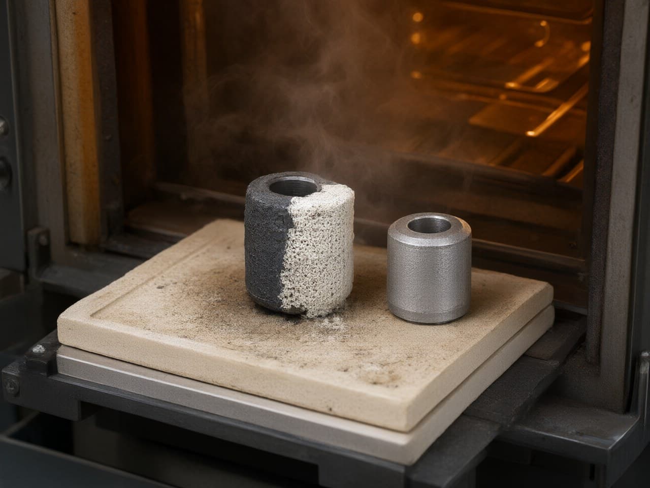
How Does Catalytic Debinding Differ from Solvent and Thermal Debinding? Which Suits 17-4PH and 316L Best?
Debinding is the highest-risk step in the metal injection molding (MIM) process chain. It determines cycle time, dimensional integrity, and—critically—whether a green part survives to sintering without cracks, blisters, or carbon contamination. Choosing the wrong binder–debinding combination for a given alloy is not merely an efficiency problem; it can add furnace occupation, raise scrap, and leave latent defects that only appear after sintering. This guide compares the three dominant debinding routes by mechanism, residual chemistry, and plant burden, then maps them onto the two most widely specified MIM stainless steels: 17-4PH and 316L.
The DFM Decision Starts with Binder Chemistry, Not Part Geometry Alone
Design-for-manufacturability in MIM is often reduced to wall thickness and draft-angle discussions. In practice, the binder system constrains the entire downstream process. A polyacetal (POM)-based feedstock is intended for catalytic debinding; a wax–polyethylene or PEG-based feedstock opens solvent or purely thermal routes. That choice cascades into furnace capital, cycle time, atmosphere control, and residual carbon—each of which affects final properties differently for austenitic 316L versus precipitation-hardening 17-4PH.
Catalytic Debinding Removes Binder at a Receding Front; Solvent and Thermal Routes Do Not
| Attribute | Catalytic (nitric-acid / oxalic-acid vapor) | Solvent (organic or water-based) | Thermal (slow pyrolysis) |
|---|---|---|---|
| Primary binder removed | POM (polyacetal) depolymerized by acid vapor | Wax / PEG dissolved into a solvent bath | All organics pyrolyzed in a furnace |
| Reaction type | Acid-catalyzed unzipping of POM → formaldehyde gas | Dissolution and diffusion through the compact | Thermal cracking and volatilization |
| Typical temperature | 110–140 °C | 40–70 °C (solvent bath) | 200–600 °C (staged ramp) |
| Cycle time (literature-typical, common MIM walls) | A few hours; published front speeds often on the order of 1–2 mm/h | Several hours to about one day of soak, plus thermal backbone burnout | On the order of 24–48 h of furnace occupation |
| Atmosphere | N₂ plus acid vapor; exhaust requires scrubbing | Air or N₂ over the solvent bath | H₂, N₂, or vacuum |
| Residual carbon risk | Low—POM is removed nearly completely before sintering | Moderate—the insoluble backbone still needs a thermal burnout | Higher unless the ramp and atmosphere are tightly controlled |
| Dimensional risk | Low—the solid backbone holds shape during catalysis | Moderate—solvent swelling of the backbone is possible | Higher—gravity slump while the binder is soft |
| Capital / EHS burden | Dedicated catalytic furnace; acid-fume and formaldehyde handling | Solvent recovery or water treatment | Standard vacuum/atmosphere furnace; long occupation |
| Best suited for | High-volume, tight-tolerance parts that need low residual carbon | Medium volume; water-soluble PEG systems reduce organic-solvent load | Low volume or very large parts when special binder chemistry is not justified |
The practical distinction is the way binder leaves the compact. Catalytic POM removal proceeds as a sharp, receding reaction front: binder is consumed from the surface inward while a polyolefin backbone keeps the particle skeleton rigid. Solvent debinding is concentration-gradient diffusion of the soluble fraction, so soak time is sensitive to the longest diffusion path and the backbone can swell. Thermal debinding heats the entire compact at once, so softening, gas evolution, and carbonaceous residue compete in the same temperature window. That front-propagation behavior is why catalytic debinding is the usual choice when dimensional scatter and residual carbon must both stay tight.
Debinding Time Grows with Wall Thickness, and the Scaling Is Not the Same for Every Route
Catalytic POM debinding is described in the MIM literature as a receding-front, shrinking-core process. At typical acid-vapor conditions the front often advances at a nearly constant speed for common wall thicknesses; as the already-debound porous shell thickens, acid-vapor diffusion adds resistance and the rate can fall off. The design consequence is milder than solvent extraction: a thicker section takes longer, but time does not explode with the square of wall thickness.
Solvent extraction of wax or PEG is diffusion-controlled. The characteristic time scales as , where is the longest diffusion half-length and is the effective diffusivity of solvent and soluble binder in the remaining matrix. Doubling the governing wall thickness therefore on the order of quadruples soak time—a severe penalty for thick bosses, unused gates, or poorly placed thick-to-thin transitions. A subsequent thermal step is still required to remove the insoluble backbone.
What this means for design and cost: For a part whose maximum wall is a few millimetres, catalytic debinding is typically finished in a few hours, whereas a wax-based solvent route needs a long soak plus backbone burnout, and a thermal-only route can occupy a furnace for a day or more. At high production volume, furnace occupation often dominates conversion cost, so the shorter catalytic cycle is usually the economic driver. At lower volume, a solvent or thermal route may win on simpler capital and EHS. Any numerical breakeven is plant-specific and should be costed from actual furnace loading, not from a generic percentage.
17-4PH Favors Catalytic Debinding, While 316L Accepts a Wider Process Window
17-4PH is a martensitic precipitation-hardening steel. After an H900-type age, MIM 17-4PH ultimate tensile strength in MPIF 35 / ASTM B883 data is typically in the 1,000–1,200 MPa range. That aging response is carbon-sensitive: residual carbon near or above the alloy limit (0.07 wt% C max in common MIM 17-4PH specifications) promotes retained austenite, suppresses martensite, and lowers hardness. Catalytic debinding of a POM-based feedstock is the preferred primary route because:
- Near-complete POM removal leaves little residual carbon for the sintering furnace to manage. - Only a small volume fraction of backbone polymer (commonly a polyolefin) remains, and that fraction is burned out on the early sintering ramp, usually under hydrogen, where carbon pickup can be controlled. - The receding-front mechanism helps hold the sintered tolerance window typical of well-controlled MIM—about ±0.3 % to ±0.5 % of nominal—which is the range specified for many 17-4PH fasteners, instruments, and structural small parts.
316L is an austenitic stainless steel specified at 0.03 wt% C max in ASTM B883 / MPIF 35 MIM-316L. It does not depend on a martensitic aging reaction, so it is more forgiving of residual carbon than 17-4PH on mechanical grounds—but carbon still matters for corrosion (sensitization and inclusion cleanliness). Both catalytic and solvent routes are viable:
- Catalytic debinding remains the fastest route for high-volume 316L and is the default at scale. - Solvent debinding (including water-based PEG systems) is a practical alternative when acid-vapor EHS is restricted, or when a water-soluble binder is already required by the plant. - Very thin walls are not a reason to avoid catalysis; they debind quickly. The process risk is the opposite: acid exposure must be sized to the thickest section so thin ligaments are not held in acid vapor long after POM is gone. Thermal-only debinding is feasible for 316L prototypes or low-volume runs, but residual carbon still has to be checked against the 0.03 wt% limit for corrosion-critical parts.
| Alloy | Recommended primary route | Acceptable alternative | Avoid as the default |
|---|---|---|---|
| 17-4PH | Catalytic (POM-based feedstock) | Solvent + thermal, with lot carbon verified inside specification | Thermal-only without demonstrated carbon control |
| 316L | Catalytic (POM-based, high volume) | Solvent (PEG-based, moderate volume or restricted acid-vapor EHS) | Thermal-only at production scale (cycle time and furnace occupation) |
Debinding Still Fails When Geometry, Atmosphere, or Carbon Limits Are Ignored
The right binder–debinding pairing does not eliminate risk. The failure modes below are the ones repeatedly seen in production, not hypothetical mechanisms:
- Catalytic cracking at abrupt thickness changes. A 1 mm flange on a 6 mm boss finishes POM removal while the thick section is still binder-rich, so shrinkage and gas flow are mismatched. Keep wall-thickness ratios below about 3:1 where the function allows, and avoid using acid exposure long enough for the thickest section if that overexposes the thinnest. - Solvent swelling and distortion. Some organic solvents swell the backbone before the primary wax or PEG is fully extracted. Water-based PEG systems reduce organic-solvent load and often reduce swell, at the cost of slower extraction. - Carbon trapped in 17-4PH. If the thermal burnout after solvent or catalytic extraction is too aggressive, carbonaceous residue is sealed into closing porosity. For 17-4PH this shows up as retained austenite and a weak aging response, even when the part looks dimensionally acceptable. - Gravity slump in thermal debinding. Pure thermal pyrolysis holds the compact for a long time in the 300–500 °C band while the binder is progressively weaker. Long cantilevers and unsupported spans can sag.
When MIM is the wrong process for these alloys: If a 17-4PH part is well outside the usual MIM mass and wall window—parts of order 100 g and walls above about 10 mm are already at the edge of common practice—debinding time and defect risk rise on every route; investment casting is often the more honest alternative. If a 316L application imposes implant-grade or extra-low-carbon chemistry (for example ASTM F138-type limits) plus full lot traceability, the entire debinding–sintering chain must be validated with carbon analysis; at low volume, machining from wrought bar may be cheaper than qualifying that chain.
Newlife - MIM Controls Debinding Quality by Matching Binder Chemistry to Each Alloy Family
Newlife - MIM runs an in-house chain from feedstock compounding through sintering and post-processing, so the binder is chosen for the alloy rather than taken as a generic catalogue grade. For 17-4PH and 316L specifically:
- Alloy-specific feedstock on fine, tightly classified powder. Particle size and solids loading are set so that, after the primary binder leaves, the remaining pore channels stay uniform enough to finish catalytic or solvent extraction without skeleton collapse. Homogeneous brown parts are what make subsequent carbon control on 17-4PH repeatable; the carbon benefit comes from binder chemistry and sintering atmosphere, not from a claimed powder trademark. - Dimensional control inside the normal MIM window. Optimized catalytic (or solvent-plus-thermal) parameters and sintering profiles are used to hold relative density in the structural-MIM range typical of ASTM B883 / MPIF 35 stainless grades and sintered tolerances of about ±0.3 % to ±0.5 % of nominal. Newlife - MIM states a sintering fleet of more than 20 furnaces and a production capacity exceeding 55 million parts per month, so those controls are intended for automotive-scale loading, not only for laboratory lots.
The Newlife - MIM application engineering team validates new part numbers with carbon-analysis sampling at the debound (brown) stage and after sintering, so the chosen debinding route can be shown to meet the alloy’s compositional limits.
Match the Debinding Route to Your Alloy Before Tooling Commits
1. Audit carbon sensitivity. For 17-4PH, default to catalytic debinding with a POM-based feedstock unless a plant constraint rules it out. 2. Map the wall-thickness profile. Use the scaling of solvent extraction to decide whether soak time is acceptable for the thickest section; do not size the cycle on the nominal wall alone. 3. Quantify volume. At automotive or consumer-electronics volumes, the shorter catalytic cycle usually dominates conversion cost. At low volume, solvent or thermal routes may offer a lower capital entry. 4. Request a debinding feasibility review from Newlife - MIM. Share the 3D model and alloy specification. The Newlife - MIM application engineering team will recommend a binder system, estimate debinding time for the actual geometry, and compare route cost on that part—not on a generic percentage.
Visit https://www.newlifematerial.com to request an engineering consultation. Whether the task is moving a CNC-machined 17-4PH component to MIM or scaling a 316L consumer-electronics part, Newlife - MIM’s feedstock-to-finished-part chain is set up so the debinding route is chosen before tooling is cut.
References
1. German, R. M. Metal Injection Molding: A Comprehensive MIM Design Guide. Metal Powder Industries Federation, 2011. 2. Heaney, D. F. (Ed.). Handbook of Metal Injection Molding. Woodhead Publishing, 2012. 3. Barriere, T., Liu, B., & Gelin, J. C. "Determination of the optimal process parameters in metal injection molding from experiments and numerical modeling." Journal of Materials Processing Technology, 143–144, 2003, pp. 636–644. 4. Luo, T. G., & Qu, X. H. "Catalytic debinding of powder injection molded compacts." Transactions of Nonferrous Metals Society of China, 12(4), 2002, pp. 656–659. 5. ASTM B883. Standard Specification for Metal Injection Molded (MIM) Materials. ASTM International (use the current edition for carbon limits and typical properties). 6. MPIF Standard 35. Materials Standards for Metal Injection Molded Parts. Metal Powder Industries Federation (17-4PH and 316L property and composition tables).
<!-- JSON-LD: {"@context": "https://schema.org", "@type": "TechArticle", "headline": "How Does Catalytic Debinding Differ from Solvent and Thermal Debinding? Which Suits 17-4PH and 316L Best?", "inLanguage": ["en", "zh"], "keywords": "catalytic debinding vs solvent thermal debinding MIM, 17-4PH MIM debinding process selection, 316L stainless steel MIM catalytic debinding, metal injection molding binder system comparison, MIM debinding defect prevention", "about": [{"@type": "Thing", "name": ""}, {"@type": "Thing", "name": ""}], "author": {"@type": "Organization", "name": "Newlife - MIM", "alternateName": "新莱福MIM应用工程团队"}, "publisher": {"@type": "Organization", "name": "Newlife - MIM", "url": "https://www.newlifematerial.com"}} -->