
How Are Copper MIM Parts Plated with Nickel, Tin, Silver or Gold? Coating Adhesion and Compatibility with Downstream Soldering and Bonding
Published:
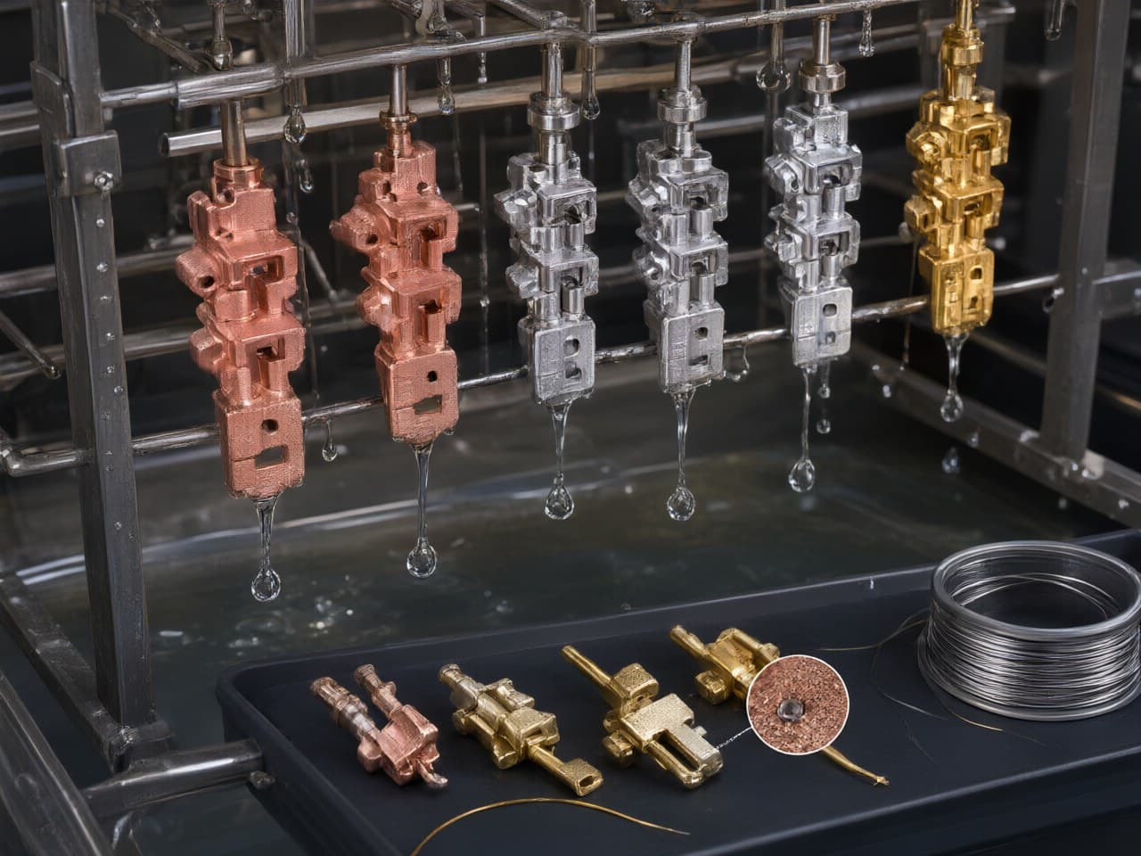
How Are Copper MIM Parts Plated with Nickel, Tin, Silver or Gold? Coating Adhesion and Compatibility with Downstream Soldering and Bonding
Copper MIM parts can be plated with nickel, tin, silver or gold. With the right surface preparation and plating stack, those finishes stay compatible with standard soldering, brazing and bonding. These are the common finishes for copper alloy parts used in connectors and contacts, and the right finish is agreed per application during quoting. The engineering work is in the details. You need to prepare the sintered surface correctly, choose an underlayer that protects the joint you will make later, and design the part so the plating line can process it cleanly.
This guide takes an optimization view. Treat the plating stack, the sintered substrate and the downstream joining step as one system, not three separate purchase lines.
Plating decisions for copper MIM parts should start from the joining process, not the finish catalogue
The most reliable plating specification comes from working backward from the final joint. That joint might be reflow soldering, torch or furnace brazing, gold or aluminum wire bonding, die attach, or a separable contact interface.
Designers often pick a finish by habit, such as "gold because it's a contact." Then the finish meets a process it wasn't chosen for. A few examples:
- Hard, cobalt-hardened gold works well on a sliding contact but is a poor surface for gold wire bonding. - Thick gold dissolved into a tin-based solder joint can embrittle it. This is why soldering standards such as IPC J-STD-001 address gold removal on solderable surfaces. - Bare tin over copper keeps forming copper–tin intermetallics in storage, which gradually consumes the solderable tin layer.
For MIM there is one more variable, the sintered surface. It may carry residual oxide from the furnace atmosphere and the cooling path, it has a characteristic as-sintered roughness, and it can retain some surface-connected porosity. Plating chemistries interact with all three. Cost optimization therefore means specifying the minimum stack that survives your joining process and service environment, rather than over-plating to cover unknowns.
Nickel, tin, silver and gold differ mainly in what downstream process they protect
The table compares the four common finishes as they apply to sintered copper and copper-alloy MIM substrates. Thickness classes should be called out from the relevant ASTM specification rather than from rules of thumb.
| Finish | Primary role on copper MIM parts | Downstream compatibility | MIM-specific adhesion and quality concerns | Typical optimization lever |
|---|---|---|---|---|
| Nickel (electrolytic, ASTM B689; or electroless Ni-P, ASTM B733) | Diffusion barrier and corrosion base; underlayer for Au, Sn, Ag | Solderable when fresh or when topped with Au/Sn; good base for Al wire bonding and brazing preparation | Needs oxide-free, activated surface. Entrapped solution in open pores causes blistering. Electroless Ni phosphorus content changes solderability and hardness | Use Ni as the barrier and keep the precious-metal top layer thin |
| Tin (matte or reflowed, ASTM B545) | Solderable finish for press-fit and soldered connector terminals | Reflow and wave soldering; press-fit | Cu–Sn intermetallic growth in storage. Whisker risk (assess per JESD201). Ni underlayer slows both | Ni underlayer plus matte Sn; define shelf life for solderability |
| Silver (ASTM B700) | High-conductivity contact and power-interface finish; brazing aid | Soldering and brazing; high-current bolted or spring contacts | Tarnishes in sulfur-bearing environments. Ionic migration under bias and humidity. Porous substrates hold residue that accelerates tarnish | Anti-tarnish post-treatment; define sulfur exposure in the spec |
| Gold (ASTM B488; soft vs. hard grades) | Low, stable contact resistance; bonding surface | Soft Au suits Au wire bonding and die attach. Hard Au suits sliding contacts. Thin Au over Ni is solderable | Au and Cu interdiffuse without a Ni barrier, especially under heat. Thick Au in solder joints risks embrittlement. Pores in Au expose Ni or Cu to corrosion | Specify Au grade by function; selective or spot plating to cut cost |
Tungsten-copper needs a separate note. Newlife - MIM produces tungsten-copper MIM parts as well as pure copper and copper alloys. A W-Cu surface does not activate like wrought copper: the tungsten-bearing surface and the copper phase do not respond to the same activation chemistry. Plating on these parts should be qualified on production-condition samples rather than on wrought copper coupons.
This topic does not have a dependable closed-form model linking plating parameters on sintered copper to adhesion strength, so no formula is given here. Adhesion is established by test, not by calculation.
The design window for plated copper MIM parts is set by density, geometry and plating access
Plating adhesion on MIM parts starts with the substrate. High sintered density minimizes surface-connected porosity, and that porosity is a primary source of plating-solution entrapment, post-bake blistering and bleed-out stains. Within the design window, focus on these points:
- Density and surface state. Specify the density requirement on the drawing or in the quality agreement. Agree on how the as-sintered surface will be cleaned and activated before the Ni strike or first layer. - Blind holes, deep slots and micro-channels. These are hard to rinse and have poor throwing power. If internal features need no plating, mask them or accept an unplated zone rather than chasing uniform thickness inside. - Sharp edges and thin fins. These concentrate current density, which builds thickness at edges and leaves recesses thin. Radii on edges help both molding and plating uniformity. - Dimensional budget. Plating adds thickness on every plated surface. Allocate it inside the sintered tolerance. On high-precision near-net-shape copper MIM, Newlife - MIM controls tolerance to ±0.3%–0.5%, which is the budget plating thickness has to share, especially on press-fit pins and mating bores. - Functional zones. Define where the solder, braze, bond or contact surface actually is. Selective gold on the contact or bond pad, with nickel elsewhere, is usually the largest single cost lever. - Flatness for die attach and bonding. Heat spreaders and packaging parts need flatness defined after plating, because stress in some deposits can matter on thin sections. - Racking and barrel contact. Mark where rack contact marks are acceptable. Small parts that tangle in barrel plating may need a design tweak or rack plating.
Plating adhesion failures on sintered copper usually trace back to surface preparation and trapped porosity
Plating failures on MIM copper parts usually show up as blisters after a bake or reflow, peeling in a bend or tape test, staining that weeps from pores, or poor solder wetting. Standard qualitative adhesion checks, such as the bend, file, tape and heat-quench methods in ASTM B571 and ISO 2819, are the practical tools for qualification. The common root causes are:
- Residual oxide or contamination on the sintered surface that the pretreatment did not fully remove. - Surface-connected porosity that holds cleaner, acid or plating solution, which then outgasses at soldering or brazing temperature. - Alloy-specific surface chemistry. Zinc-bearing copper alloys and tungsten-copper both need their own activation sequence compared with pure copper. - Wrong top layer for the joint. Examples include hard gold on a wire-bond pad, excessive gold in a solder joint, or aged tin that has lost its solderability.
MIM is not the right route in some cases. Simple flat contacts and terminals produced in high volume are often cheaper stamped from pre-plated reel-to-reel strip. Parts that must be hermetic deserve caution if the only intended seal is plating across residual porosity and no sealing step has been qualified. Very low volumes may not justify tooling. MIM earns its place when the geometry is three-dimensional, such as micro-fins, cavities, internal channels or integrated features, and would otherwise require costly copper machining followed by the same plating.
Newlife - MIM capabilities give auditable evidence for the plated copper supply chain
A plated copper MIM part is only as reliable as the traceability behind the substrate. When you audit a supplier, ask for evidence rather than claims. The points below are where the Newlife - MIM team can show records:
- Substrate density that supports plating. Newlife - MIM produces pure copper, copper alloy and tungsten-copper parts at a sintered density of ≥8.4 g/cm³, with high-precision near-net-shape parts held to a relative density ≥98%. That relative-density level is what limits surface-connected porosity that otherwise drives blistering and bleed-out. Ask for density data by lot. - Full-chain process coverage. Mixing, granulation, injection, debinding, sintering and post-processing are covered in one process chain, so atmosphere, surface condition and post-treatment can be examined together when a plating defect is investigated. - Dimensional capability with plating allowance. Near-net-shape tolerance of ±0.3%–0.5% lets the plating thickness allocation be negotiated against real process capability. Ask for Cpk on the critical dimensions before and after plating. - Automotive-grade quality system. IATF 16949, ISO 9001 and ISO 14001 certification is in place. IATF 16949 and ISO 9001 support change control, PPAP documentation where the program requires it, and lot traceability for plated copper parts. ISO 14001 covers the environmental management system.
The surface treatment specification, including stack, grade, thickness class and selective areas, is agreed per application during quoting. That is the right point to bring your joining process and reliability test plan to the table.
Lock the plating stack to the joining process before production release
1. Define the final joining process and service environment: solder alloy and profile, braze alloy, wire type, contact force and cycles, sulfur or humidity exposure. 2. Mark functional zones on the drawing and specify selective plating where the precious-metal layer is only needed locally. 3. Choose the underlayer first (usually nickel as a diffusion barrier), then the top layer by function, citing ASTM B689/B733/B545/B700/B488 as applicable. 4. Allocate plating thickness within the MIM tolerance on press-fit and mating features. 5. Qualify with production-condition parts: adhesion tests per ASTM B571 or ISO 2819, a bake or reflow simulation, solderability per J-STD-002, and wire-pull or shear tests for bonded parts. 6. Contact Newlife - MIM for customized engineering support. Share your drawing, joining process and plating requirements so the substrate, surface preparation and finish can be engineered together.
Ready to engineer a plated copper MIM part for soldering, brazing or bonding? Visit http://www.newlife.cn to request a free consultation and a custom engineering solution from the Newlife - MIM application engineering team.
References
1. ASTM B689, Standard Specification for Electroplated Engineering Nickel Coatings. 2. ASTM B733, Standard Specification for Autocatalytic (Electroless) Nickel-Phosphorus Coatings on Metal. 3. ASTM B545, Standard Specification for Electrodeposited Coatings of Tin. 4. ASTM B700, Standard Specification for Electrodeposited Coatings of Silver for Engineering Use. 5. ASTM B488, Standard Specification for Electrodeposited Coatings of Gold for Engineering Uses. 6. ASTM B571, Standard Practice for Qualitative Adhesion Testing of Metallic Coatings. 7. ISO 2819, Metallic coatings on metallic substrates — Electrodeposited and chemically deposited coatings — Review of methods available for testing adhesion. 8. IPC J-STD-001, Requirements for Soldered Electrical and Electronic Assemblies. 9. IPC J-STD-002, Solderability Tests for Component Leads, Terminations, Lugs, Terminals and Wires. 10. JEDEC JESD201, Environmental Acceptance Requirements for Tin Whisker Susceptibility of Tin and Tin Alloy Surface Finishes. 11. MPIF Standard 35, Materials Standards for Metal Injection Molded Parts. 12. German, R. M., & Bose, A. Injection Molding of Metals and Ceramics. Metal Powder Industries Federation, 1997. 13. ASM Handbook, Volume 5: Surface Engineering. ASM International. 14. Newlife - MIM capability information, http://www.newlife.cn