
Debinding and Sintering: The Critical Processes That Determine MIM Part Density
Published:
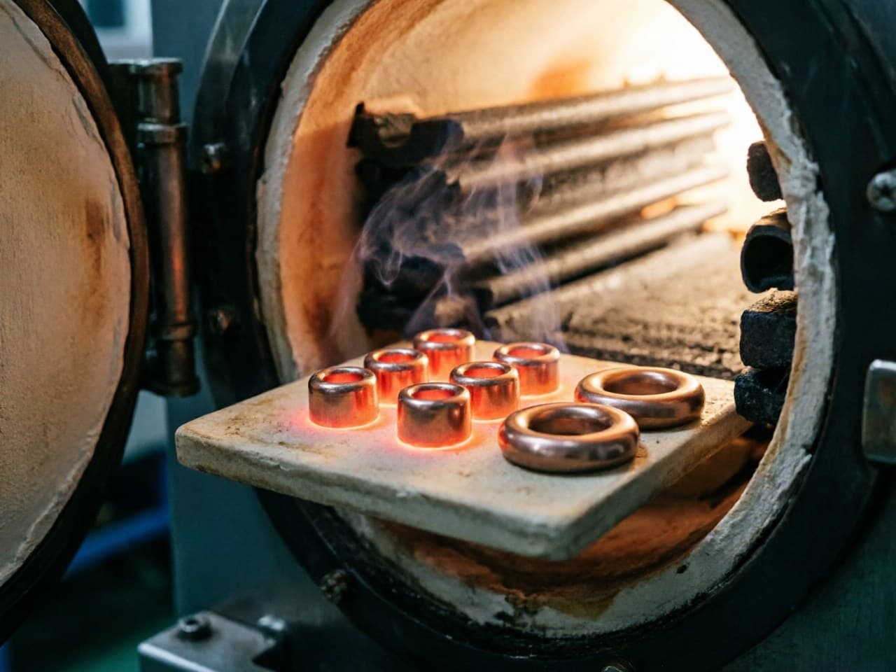
Debinding and Sintering: The Critical Processes That Determine MIM Part Density
Author: Newlife - MIM (新莱福MIM应用工程团队) | Material: | Industry:
Debinding and Sintering:
The Critical Processes That Determine MIM Part Density
Application Pain Points:
Why Density Control Remains the Top MIM Engineering Challenge
Metal Injection Molding (MIM) promises complex geometries at scale—but the promise lives or dies in two back-end process steps: debinding and sintering. These operations convert a fragile "green part" (typically 60–65 vol.% metal powder in a polymer binder) into a fully dense, mechanically competent component. Get them wrong, and the consequences are severe:
- Residual porosity degrades tensile strength, fatigue life, and corrosion resistance—often invisibly, discovered only during field failures. - Dimensional distortion during sintering (parts shrink 15–22% linearly) can push tolerances beyond specification, generating scrap. - Carbon contamination from incomplete binder removal alters alloy chemistry, causing phase instability in stainless steels and soft-magnetic alloys. - Regulatory non-compliance: Automotive (IATF 16949), medical (ISO 13485), and firearms standards impose minimum sintered density thresholds—often ≥ 96% theoretical density (TD) and frequently ≥ 98% TD for safety-critical parts. Failure to demonstrate process capability against these thresholds blocks qualification entirely.
Design engineers and procurement teams frequently underestimate how tightly debinding and sintering parameters interact. A change in binder system forces a new thermal profile; a new powder lot shifts optimal sintering temperature by 20–40 °C. Without rigorous process control, density scatter between batches can exceed 2% TD—enough to fail incoming inspection under ASTM B883 (Standard Specification for Metal Injection Molded Parts) or MPIF Standard 35.
---
Debinding and Sintering Methods: A Selection Comparison
The following table summarizes the dominant debinding and sintering approaches, their density outcomes, and regulatory relevance.
Parameter | Solvent + Thermal Debinding → Vacuum Sintering | Catalytic Debinding (e.g., HNO₃) → H₂ Sintering | Purely Thermal Debinding → Continuous Belt Sintering |
Typical binder system | Wax/polyolefin + backbone polymer | Polyacetal (POM)-based | Wax/polymer blends |
Debinding temperature range | Solvent: 40–70 °C; Thermal: 200–600 °C | Catalytic: 110–140 °C (HNO₃ vapor) | 200–650 °C (single ramp) |
Debinding time (illustrative) | 6–12 h solvent + 4–8 h thermal | 4–8 h catalytic + 1–2 h thermal | 10–20 h continuous |
Sintering atmosphere | Vacuum (10⁻²–10⁻⁴ mbar) or partial-pressure Ar/H₂ | H₂ or H₂/N₂ mix | H₂/N₂ (90/10 or 75/25) |
Peak sintering temperature | 1 250–1 380 °C (alloy-dependent) | 1 250–1 380 °C | 1 200–1 350 °C |
Achievable relative density | ≥ 97–99% TD | ≥ 96–98.5% TD | 93–96% TD |
Carbon control capability | Excellent (vacuum gettering) | Good (atmosphere control) | Moderate |
Dimensional tolerance (±) | 0.3–0.5% | 0.3–0.5% | 0.5–1.0% |
Regulatory suitability | IATF 16949, ASTM B883 Class 1 | ASTM B883 Class 1–2, ISO 13485 capable | ASTM B883 Class 2–3 (non-critical) |
Capital & operating cost | High (vacuum furnaces) | Medium–High (acid handling, safety) | Lower (belt furnace) |
Best fit | High-density, tight-tolerance, safety-critical | High-volume automotive, consumer electronics | Cost-sensitive, lower-density-acceptable parts |
Key takeaway for procurement: If your specification calls for ≥ 98% TD and compliance with IATF 16949 or ASTM B883 Class 1, the solvent-plus-thermal debinding route paired with vacuum or controlled-atmosphere sintering in batch furnaces is the process of record. Continuous belt sintering rarely achieves the density ceiling required by automotive or medical standards.
---
First-Principles Derivation: The Physics Governing Density
Principle 1 — Diffusion-Driven Densification (Sintering Kinetics)
Sintering densification is fundamentally a solid-state diffusion process. The classical Herring scaling law relates the time *t* required to reach a given density to particle diameter *D*:
where *n* = 3 for volume (lattice) diffusion and *n* = 4 for grain-boundary diffusion.
What this means for your design: Halving the powder particle size (e.g., from D50 = 10 µm to D50 = 5 µm) can reduce the sintering time to reach 98% TD by a factor of roughly 8× (volume diffusion) or 16× (grain-boundary diffusion). Alternatively, finer powder reaches *higher* final density at the same temperature and time. This is why ultra-fine powders (D50 ≤ 3 µm) are a direct lever for meeting stringent density specifications—though they demand tighter debinding control to avoid cracking from higher green-body packing stresses.
Principle 2 — Binder Removal Rate and Defect Formation
During thermal debinding, the binder decomposes into gaseous species that must diffuse out through a porous powder skeleton. The maximum safe heating rate *β_max* is governed by the permeability of the partially debound compact and the internal vapor pressure. A simplified relationship:
where *k* is the skeleton permeability, *P_ext* is the external (furnace) pressure, *η* is the gas viscosity, and *L* is the maximum wall thickness of the part.
What this means for your design: Thicker cross-sections require slower heating ramps during debinding—or a preceding solvent/catalytic step to open porosity channels first. Ignoring this relationship causes internal pressure build-up, leading to blistering, bloating, or micro-cracks that persist through sintering and reduce final density by 1–4% TD. For parts with wall sections exceeding 6–8 mm, a two-stage debinding protocol is essentially mandatory to meet ≥ 97% TD.
---
Design Parameter Recommendations
Based on the principles above and prevailing industry standards (ASTM B883, MPIF 35, IATF 16949 process audit requirements), the following parameter windows are recommended:
Design / Process Parameter | Recommended Range | Regulatory Rationale |
Powder D50 | 3–12 µm (≤ 5 µm preferred for ≥ 98% TD) | Finer powder directly enables ASTM B883 Class 1 density |
Solvent debinding duration | Until ≥ 50–70% binder removal confirmed (mass loss) | Ensures open porosity for safe thermal debinding; prevents defects flagged in IATF 16949 PFMEA |
Thermal debinding ramp rate | 0.5–3 °C/min (thicker walls → slower) | Prevents internal cracking; validated per ASTM E3166 (thermal analysis) |
Sintering peak temperature | Alloy-specific; e.g., 316L SS: 1 340–1 380 °C; Fe-2Ni: 1 280–1 320 °C | Must be documented in control plan per IATF 16949 §8.5.1 |
Sintering hold time | 1–4 h at peak temperature | Longer holds close residual porosity; diminishing returns beyond 4 h |
Sintering atmosphere dew point | ≤ −40 °C (H₂ or vacuum ≤ 10⁻³ mbar) | Controls oxide/carbon; required for corrosion-resistance per ASTM A276 equivalence |
Target relative density | ≥ 98% TD for structural/safety-critical; ≥ 96% for general | Per ASTM B883 classification and OEM-specific SORs |
Post-sintering dimensional tolerance | ± 0.3–0.5% of nominal | IATF 16949 Cpk ≥ 1.67 expectation for critical dimensions |
---
Newlife - MIM Solution: Density-Assured Production at Scale
Achieving ≥ 98% relative density consistently across production volumes requires integrated process control from powder to finished part. The Newlife - MIM application engineering team addresses the debinding and sintering challenge through the following directly relevant capabilities:
1. In-house metal powder and feedstock development Control of particle-size distribution and feedstock formulation enables tuning of debinding kinetics and sintering shrinkage for each alloy–geometry combination. Tighter particle-size distributions support higher sintered density and reduced dimensional scatter, consistent with ASTM B883 Class 1 and typical OEM Cpk targets.
2. End-to-end MIM process ownership Ownership of the full process chain from mixing through debinding and sintering eliminates interface risks associated with outsourced thermal operations. Thermal profiles are validated against each feedstock lot to maintain binder removal rates and atmospheres within qualified windows, supporting IATF 16949 process-control expectations.
3. Near-net-shape process capability Documented temperature uniformity, atmosphere monitoring, and statistical process control on density (Archimedes method per ASTM B962) for production lots support the density and dimensional performance required by automotive and medical OEMs.
4. Quality-system certifications IATF 16949, ISO 9001, and ISO 14001 certifications require living control plans, PFMEA for debinding and sintering failure modes, measurement-system analysis, and lot traceability—reducing qualification risk for procurement teams.
---
Action Checklist for Design Engineers and Procurement Teams
1. Define your density requirement explicitly in the part specification—state the minimum relative density (% TD), the test method (ASTM B962 Archimedes or ASTM E1019 gas pycnometry), and the acceptance sampling plan.
2. Specify the debinding method in your process flow requirement or allow the supplier to propose—but require documented PFMEA for binder removal failure modes (blistering, carbon residue, cracking).
3. Request sintering furnace temperature uniformity data and atmosphere dew-point records as part of supplier qualification; these are leading indicators of density capability.
4. Verify the supplier's powder and feedstock control—in-house powder production with controlled particle-size distribution is a strong predictor of consistent high-density achievement.
5. Audit against IATF 16949 or equivalent—ensure the supplier maintains statistical process control on sintered density with Cpk ≥ 1.33 (preferably ≥ 1.67) for safety-critical applications.
6. Contact Newlife - MIM for engineering consultation. Submit part drawings, density specifications, and regulatory requirements for a process feasibility assessment and material recommendation.
---
References
1. ASTM B883 – Standard Specification for Metal Injection Molded (MIM) Parts. ASTM International. 2. MPIF Standard 35 – Materials Standards for Metal Injection Molded Parts. Metal Powder Industries Federation. 3. ASTM B962 – Standard Test Methods for Density of Compacted or Sintered Powder Metallurgy Products Using Archimedes' Principle. ASTM International. 4. IATF 16949:2016 – Quality Management System Requirements for Automotive Production and Relevant Service Parts Organizations. 5. German, R. M. *Sintering: From Empirical Observations to Scientific Principles*. Butterworth-Heinemann, 2014. 6. Heaney, D. F. (Ed.). *Handbook of Metal Injection Molding*, 2nd Edition. Woodhead Publishing, 2019. 7. Herring, C. "Effect of Change of Scale on Sintering Phenomena." *Journal of Applied Physics*, 21(4), 301–303, 1950. 8. AMS 2750 – Pyrometry. SAE International.